
Guide


3/7/2018 SparkFun Inventor's Kit for micro:bit Experiment Guide - learn.sparkfun.com
https://learn.sparkfun.com/tutorials/sparkfun-inventors-kit-for-microbit-experiment-guide/all#introduction-to-microsoft-makecode 14/63
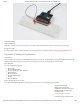
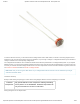
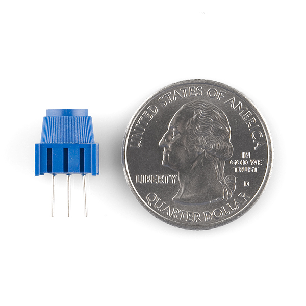
To hook up the potentiometer, attach the two outside pins to a supply voltage (3.3V in this circuit) and ground. It doesn’t matter
which is connected where, as long as one is connected to power, and the other to ground. The center pin is then connected to an
analog input pin so the micro:bit can measure the change in voltage. When you twist the knob, the sensor reading will change!
Note: The potentiometer included in the kit has three marks on it that will help you figure out which breadboard rows the pins
are plugged into.
Hardware Hookup
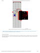
Ready to start hooking everything up? Check out the wiring diagram and hookup table below to see how everything is connected.
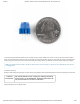
Polarized
Components
Pay special attention to the component’s markings indicating
how to place it on the breadboard. Polarized components can
only be connected to a circuit in one direction.
Wiring Diagram for the Experiment