
Data Sheet

58 : circuit 3a
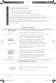
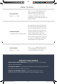
SERVO ATTACH:
myServo.attach(9);
The .attach(); method tells the servo
object to which pin the signal wire is
attached. It will send position signals
to this pin. In this sketch, pin 9 is used.
Remember to only use digital pins that are
capable of PWM.
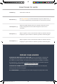
RANGE MAPPING:
map(potPosition,0,1023,20,160);
As shown in previous circuits, the analog
pin values on your microcontroller vary
from 0 to 1023. But what if we want those
values to control a servo motor that only
accepts a value from 0 to 180? The map()
function takes a range of values and
outputs a different range that can contain
more or fewer values than the original. In
this case, we are taking the range 0–1023
and mapping it to the range 20–160.
SERVO WRITE:
myServo.write(90);
The .write(); method moves the servo
to a specified angle. In this example, the
servo is being told to go to angle 90.
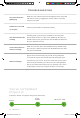
CODING CHALLENGES
REVERSE THE SERVO DIRECTION: Try making the servo move in the opposite
direction of the potentiometer.
CHANGE THE RANGE: Try altering the map function so that moving the potentiometer
a lot only moves the servo a little or vice versa.
SWAP IN A DIFFERENT SENSOR: Try swapping a light sensor in for the
potentiometer. Then you can make a dial that reads how much light is present!
CODE TO NOTE
SIK v4 Book Oct 13.indb 58 10/18/17 10:00 AM