
Data Sheet


4 : intro
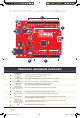
IOREF
RESET
RESET
7-15V
SCL
SDA
AREF
GND
13
12
~11
~10
~9
8
7
~6
~5
4
~3
2
1
0
TX
RX
13
3.3V
5V
GND
GND
VIN
A0
A1
A2
A3
A4
A5
POWER ANALOG IN
DIGITAL (PWM~)
ON
ISP
TX
RX
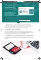
START SOMETHING
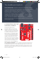
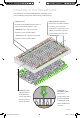
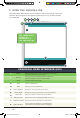
Anatomy of the SparkFun RedBoard
REDBOARD HARDWARE OVERVIEW
A
POWER IN
(BARREL JACK)
Can be used with either a 9V or 12V “wall-wart” or a battery pack.
B
POWER IN
(USB PORT)
Provides power and communicates with your board
when plugged into your computer via USB.
C
LED
(RX: RECEIVING)
Shows when the FTDI chip is receiving data bits from the computer.
D
LED
(TX: TRANSMITTING)
Shows when the FTDI chip is transmitting data bits to the computer.
E
ONBOARD LED
PIN D
This LED, connected to digital pin 13, can be controlled
in your program and is great for troubleshooting.
F
PINS AREF,
GROUND, DIGITAL,
RX, TX, SDA, SCL
These pins can be used for inputs, outputs, power and ground.
G
POWER LED
Illuminated when the board is connected to a power source.
H
RESET BUTTON
A manual reset switch that will restart the RedBoard and your code.
I
ISP HEADER
This is the In-System Programming header. It is used to program the ATMega328
directly. It will not be used in this guide.
J
ANALOG IN,
VOLTAGE IN,
GROUND, . AND
V OUT, RESET
The power bus has pins to power your circuits with various voltages. The analog
inputs allow you to read analog signals.
K
RFU
This stands for Reserved for Future Use.
A
B
C
D
E
F
H
I
J
G
K
SIK v4 Book Oct 13.indb 4 10/18/17 9:58 AM