
Data Sheet


20 : circuit 1b
NEW COMPONENTS
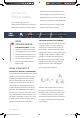
POTENTIOMETER: A potentiometer is
a 3-pin variable resistor. When powered
with 5V, the middle pin outputs a voltage
between 0V and 5V, depending
on the position of the knob on
the potentiometer. Internal to the
trimpot is a single resistor and a
wiper, which cuts the resistor in two and
moves to adjust the ratio between
both halves.
NEW CONCEPTS
ANALOG VS. DIGITAL: We live in an
analog world. There are an infinite number
of colors to paint an object, an infinite
number of tones we can hear, and an
infinite number of smells we can smell.
The common theme among these analog
signals is their infinite possibilities.
Digital signals deal in the realm of the
discrete or finite, meaning there is a
limited set of values they can be. The LED
from the previous circuit had only two
states it could exist in, ON or OFF, when
connected to a digital output.
ANALOG INPUTS: So far, we’ve only
dealt with outputs. The RedBoard also has
inputs. Both inputs and outputs can be
analog or digital. Based on our previous
definition of analog and digital, that means
an analog input can sense a wide range of
values versus a digital
input, which can only
sense two values, or
states.
You may have noticed
some pins labeled
Digital and some
labeled Analog In on
your RedBoard. There are only six pins
that function as analog inputs; they are
labeled A0–A5.
VOLTAGE DIVIDER
VOLTAGE DIVIDERS are simple
circuits that turn some voltage into a
smaller voltage using two resistors. A
potentiometer is a variable resistor that
can be used to create an adjustable voltage
divider. A wiper in the middle position
means the output voltage will be half of the
input. Voltage dividers will be covered in
more detail in the next circuit.
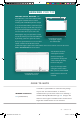
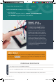
Circuit 1B:
Potentiometer
Potentiometers (also known as “trimpots”
or “knobs”) are one of the basic inputs for
electronic devices. By tracking the position
of the knob with your RedBoard, you can
make volume controls, speed controls,
angle sensors and a ton of other useful
inputs for your projects. In this circuit,
you’ll use a potentiometer as an input
device to control the speed at which your
LED blinks.
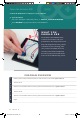
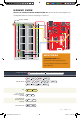
IOREF
RESET
RESET
7-15V
SCL
SDA
AREF
GND
13
12
~11
~10
~9
8
7
~6
~5
4
~3
2
1
0
TX
RX
13
3.3V
5V
GND
GND
VIN
A0
A1
A2
A3
A4
A5
POWER ANALOG IN
DIGITAL (PWM~)
ON
ISP
TX
RX
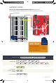
START SOMETHING
YOU
NEED
10k
100k
330
LED POTENTIOMETER RESISTOR JUMPER WIRES
SIK v4 Book Oct 13.indb 20 10/18/17 9:59 AM