
Data Sheet

Application
Processor
SCL
SDA
GPIO
ANALOG
SCL
SDA
EN
IN/TRIG
REG
OUT±
V
DD
GND
OUT+
DRV2605L
2 V ± 5.2 V
C
(REG)
C
(VDD)
M
LRA or
ERM
C
(IN)
(optional)
R
(PU)
R
(PU)
Application
Processor
SCL
SDA
GPIO
PWM/GPIO
SCL
SDA
EN
IN/TRIG
REG
OUT±
V
DD
GND
OUT+
DRV2605L
2 V ± 5.2 V
C
(REG)
C
(VDD)
M
LRA or
ERM
R
(PU)
R
(PU)
DRV2605L
SLOS854C –MAY 2014–REVISED SEPTEMBER 2014
www.ti.com
9 Application and Implementation
NOTE
Information in the following applications sections is not part of the TI component
specification, and TI does not warrant its accuracy or completeness. TI’s customers are
responsible for determining suitability of components for their purposes. Customers should
validate and test their design implementation to confirm system functionality.
9.1 Application Information
The typical application for a haptic driver is in a touch-enabled system that already has an application processor
which makes the decision on when to execute haptic effects.
The DRV2605L device can be used fully with I
2
C communications (either using RTP or the memory interface). A
system designer can chose to use external triggers to play low-latency effects (such as from a physical button) or
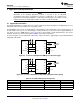
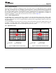
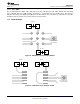
can decide to use the PWM interface. Figure 58 shows a typical haptic system implementation. The system
designer should not use the internal regulator (REG) to power any external load.
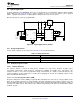
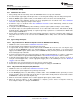
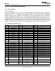
A system designer can also implement audio-to-vibe. Figure 59 shows a typical haptic system implementation
supporting audio-to-vibe.
Figure 58. I
2
C Control with Optional PWM Input or External Trigger
Figure 59. I
2
C Control With Audio-to-Vibe Input and Optional AC Coupling
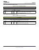
Table 32. Recommended External Components
COMPONENT DESCRIPTION SPECIFICATION TYPICAL VALUE
C
(VDD)
Input capacitor Capacitance 0.1 µF
C
(REG)
Regulator capacitor Capacitance 1 µF
C
(IN)
AC coupling capacitor (optional) Capacitance 1 µF
R
(PU)
Pullup resistor Resistance 2.2 kΩ
52 Submit Documentation Feedback Copyright © 2014, Texas Instruments Incorporated
Product Folder Links: DRV2605L