
Data Sheet

DRV2605L
SLOS854C –MAY 2014–REVISED SEPTEMBER 2014
www.ti.com
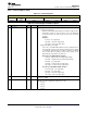
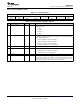
8.6.23 Control3 (Address: 0x1D)
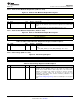
Figure 52. Control3 Register
7 6 5 4 3 2 1 0
NG_THRESH[1:0] ERM_OPEN_L SUPPLY_COM DATA_FORMA LRA_DRIVE_M N_PWM_ANAL LRA_OPEN_L
OOP P_DIS T_RTP ODE OG OOP
R/W-1 R/W-0 R/W-1 R/W-0 R/W-0 R/W-0 R/W-0 R/W-0
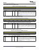
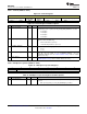
Table 26. Control3 Register Field Descriptions
BIT FIELD TYPE DEFAULT DESCRIPTION
7-6 NG_THRESH[1:0] R/W 1
This bit is the noise-gate threshold for PWM and analog inputs.
0: Disabled
1: 2%
2: 4% (Default)
3: 8%
5 ERM_OPEN_LOOP R/W 1
This bit selects mode of operation while in ERM mode. Closed-loop operation is
usually desired for because of automatic overdrive and braking properties.
However, many existing waveform libraries were designed for open-loop
operation, so open-loop operation may be required for compatibility.
0: Closed Loop
1: Open Loop
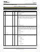
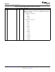
4 SUPPLY_COMP_DIS R/W 0
This bit disables supply compensation. The DRV2605L device generally
provides constant drive output over variation in the power supply input (V
DD
). In
some systems, supply compensation may have already been implemented
upstream, so disabling the DRV2605L supply compensation can be useful.
0: Supply compensation enabled
1: Supply compensation disabled
3 DATA_FORMAT_RTP R/W 0
This bit selects the input data interpretation for RTP (Real-Time Playback)
mode.
0: Signed
1: Unsigned
2 LRA_DRIVE_MODE R/W 0
This bit selects the drive mode for the LRA algorithm. This bit determines how
often the drive amplitude is updated. Updating once per cycle provides a
symmetrical output signal, while updating twice per cycle provides more precise
control.
0: Once per cycle
1: Twice per cycle
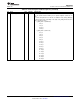
1 N_PWM_ANALOG R/W 0
This bit selects the input mode for the IN/TRIG pin when MODE[2:0] = 3. In
PWM input mode, the duty cycle of the input signal determines the amplitude of
the waveform. In analog input mode, the amplitude of the input determines the
amplitude of the waveform.
0: PWM Input
1: Analog Input
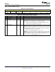
0 LRA_OPEN_LOOP R/W 0
This bit selects an open-loop drive option for LRA Mode. When asserted, the
playback engine drives the LRA at the selected frequency independently of the
resonance frequency. In PWM input mode, the playback engine recovers the
LRA commutation frequency from the PWM input, dividing the frequency by
128. Therefore the PWM input frequency must be equal to 128 times the
resonant frequency of the LRA.
In RTP, ROM and audio-to-vibe mode, the frequency is set by the
OL_LRA_PERIOD[6:0] bit. Open-loop mode is not supported if analog
input mode is selected.
0: Auto-resonance mode
1: LRA open-loop mode
48 Submit Documentation Feedback Copyright © 2014, Texas Instruments Incorporated
Product Folder Links: DRV2605L