
Data Sheet

DRV2605L
www.ti.com
SLOS854C –MAY 2014–REVISED SEPTEMBER 2014
8.6.22 Control2 (Address: 0x1C)
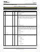
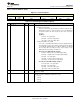
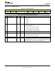
Figure 51. Control2 Register
7 6 5 4 3 2 1 0
BIDIR_INPUT BRAKE_STABI SAMPLE_TIME[1:0] BLANKING_TIME[1:0] IDISS_TIME[1:0]
LIZER
R/W-1 R/W-1 R/W-1 R/W-0 R/W-1 R/W-0 R/W-1
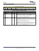
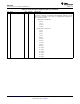
Table 25. Control2 Register Field Descriptions
BIT FIELD TYPE DEFAULT DESCRIPTION
7 BIDIR_INPUT R/W 1
The BIDIR_INPUT bit selects how the engine interprets data.
0: Unidirectional input mode
Braking is automatically determined by the feedback conditions and is
applied when needed. Use of this mode also recovers an additional bit
of vertical resolution. This mode should only be used for closed-loop
operation.
Examples::
0% Input → No output signal
50% Input → Half-scale output signal
100% Input → Full-scale output signal
1: Bidirectional input mode (default)
This mode is compatible with traditional open-loop signaling and also
works well with closed-loop mode. When operating closed-loop, braking
is automatically determined by the feedback conditions and applied
when needed. When operating open-loop modes, braking is only
applied when the input signal is less than 50%.
Open-loop mode (ERM and LRA) examples:
0% Input → Negative full-scale output signal (braking)
25% Input → Negative half-scale output signal (braking)
50% Input → No output signal
75% Input → Positive half-scale output signal
100% Input → Positive full-scale output signal
Closed-loop mode (ERM and LRA) examples:
0% to 50% Input → No output signal
50% Input → No output signal
75% Input → Half-scale output signal
100% Input → Full-scale output signal
6 BRAKE_STABILIZER R/W 1
When this bit is set, loop gain is reduced when braking is almost complete to
improve loop stability
5-4 SAMPLE_TIME[1:0] R/W 1
LRA auto-resonance sampling time (Advanced use only)
0: 150 µs
1: 200 µs
2: 250 µs
3: 300 µs
Copyright © 2014, Texas Instruments Incorporated Submit Documentation Feedback 45
Product Folder Links: DRV2605L