
Data Sheet


DRV2605L
SLOS854C –MAY 2014–REVISED SEPTEMBER 2014
www.ti.com
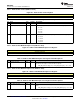
8.6.7 Overdrive Time Offset (Address: 0x0D)
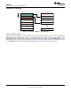
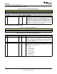
Figure 36. Overdrive Time Offset Register
7 6 5 4 3 2 1 0
ODT[7:0]
R/W-0
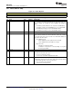
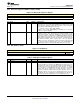
Table 10. Overdrive Time Offset Register Field Descriptions
BIT FIELD TYPE DEFAULT DESCRIPTION
7-0 ODT R/W 0
This bit adds a time offset to the overdrive portion of the library
waveforms. Some motors require more overdrive time than others, so this
register allows the user to add or remove overdrive time from the library
waveforms. The maximum voltage value in the library waveform is
automatically determined to be the overdrive portion. This register is only
useful in open-loop mode. Overdrive is automatic for closed-loop mode.
The offset is interpreted as 2s complement, so the time offset may be
positive or negative.
Overdrive Time Offset (ms) = ODT[7:0] × PLAYBACK_INTERVAL
See the Control5 (Address: 0x1F) section for PLAYBACK_INTERVAL
details.
8.6.8 Sustain Time Offset, Positive (Address: 0x0E)
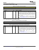
Figure 37. Sustain Time Offset, Positive Register
7 6 5 4 3 2 1 0
SPT[7:0]
R/W-0
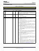
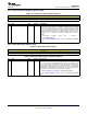
Table 11. Sustain Time Offset, Positive Register Field Descriptions
BIT FIELD TYPE DEFAULT DESCRIPTION
7-0 SPT R/W 0
This bit adds a time offset to the positive sustain portion of the library
waveforms. Some motors have a faster or slower response time than
others, so this register allows the user to add or remove positive sustain
time from the library waveforms. Any positive voltage value other than the
overdrive portion is considered as a sustain positive value. The offset is
interpreted as 2s complement, so the time offset can positive or negative.
Sustain-Time Positive Offset (ms) = SPT[7:0] ×
PLAYBACK_INTERVAL
See the Control5 (Address: 0x1F) section for PLAYBACK_INTERVAL
details.
38 Submit Documentation Feedback Copyright © 2014, Texas Instruments Incorporated
Product Folder Links: DRV2605L