
Data Sheet


DRV2605L
SLOS854C –MAY 2014–REVISED SEPTEMBER 2014
www.ti.com
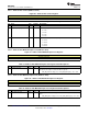
8.6.3 Real-Time Playback Input (Address: 0x02)
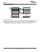
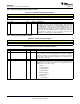
Figure 32. Real-Time Playback Input Register
7 6 5 4 3 2 1 0
RTP_INPUT[7:0]
R/W-0
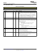
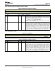
Table 6. Real-Time Playback Input Register Field Descriptions
BIT FIELD TYPE DEFAULT DESCRIPTION
7-0 RTP_INPUT[7:0] R/W 0
This field is the entry point for real-time playback (RTP) data. The
DRV2605L playback engine drives the RTP_INPUT[7:0] value to the load
when MODE[2:0] = 5 (RTP mode). The RTP_INPUT[7:0] value can be
updated in real-time by the host controller to create haptic waveforms. The
RTP_INPUT[7:0] value is interpreted as signed by default, but can be set to
unsigned by the DATA_FORMAT_RTP bit in register 0x1D. When the
haptic waveform is complete, the user can idle the device by setting
MODE[2:0] = 0, or alternatively by setting STANDBY = 1.
8.6.4 Library Selection (Address: 0x03)
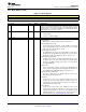
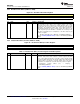
Figure 33. Library Selection Register
7 6 5 4 3 2 1 0
Reserved HI_Z Reserved LIBRARY_SEL[2:0]
R/W-0 R/W-0 R/W-0 R/W-1
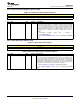
Table 7. Library Selection Register Field Descriptions
BIT FIELD TYPE DEFAULT DESCRIPTION
7-5 Reserved
4 HI_Z R/W 0
This bit sets the output driver into a true high-impedance state. The device
must be enabled to go into the high-impedance state. When in hardware
shutdown or standby mode, the output drivers have 15 kΩ to ground. When
the HI_Z bit is asserted, the hi-Z functionality takes effect immediately, even
if a transaction is taking place.
3 Reserved
2-0 LIBRARY_SEL R/W 1
Waveform library selection value. This bit determines which library the
playback engine selects when the GO bit is set. For additional details on the
ERM libraries see the Table 1 section.
0: Empty
1: TS2200 Library A
2: TS2200 Library B
3: TS2200 Library C
4: TS2200 Library D
5: TS2200 Library E
6: LRA Library
7: TS2200 Library F
36 Submit Documentation Feedback Copyright © 2014, Texas Instruments Incorporated
Product Folder Links: DRV2605L