
Data Sheet


DRV2605L
SLOS854C –MAY 2014–REVISED SEPTEMBER 2014
www.ti.com
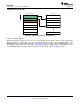
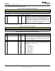
8.6.1 Status (Address: 0x00)
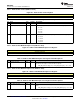
Figure 30. Status Register
7 6 5 4 3 2 1 0
DEVICE_ID[2:0] Reserved DIAG_RESULT Reserved OVER_TEMP OC_DETECT
RO-1 RO-1 RO-1 RO-0 RO-0 RO-0
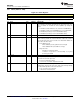
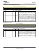
Table 4. Status Register Field Descriptions
BIT FIELD TYPE DEFAULT DESCRIPTION
7-5 DEVICE_ID[2:0] RO 7
Device identifier. The DEVICE_ID bit indicates the part number to the user.
The user software can ascertain the device capabilities by reading this
register.
4: DRV2604 (contains RAM, does not contain licensed ROM library)
3: DRV2605 (contains licensed ROM library, does not contain RAM)
6: DRV2604L (low-voltage version of the DRV2604 device)
7: DRV2605L (low-voltage version of the DRV2605 device)
4
Reserved
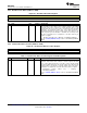
3 DIAG_RESULT RO 0
This flag stores the result of the auto-calibration routine and the diagnostic
routine. The flag contains the result for whichever routine was executed
last. The flag clears upon read. Test result is not valid until the GO bit self-
clears at the end of the routine.
Auto-calibration mode:
0: Auto-calibration passed (optimum result converged)
1: Auto-calibration failed (result did not converge)
Diagnostic mode:
0: Actuator is functioning normally
1: Actuator is not present or is shorted, timing out, or giving
out–of-range back-EMF
2 Reserved
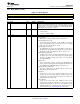
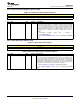
1 OVER_TEMP RO 0
Latching overtemperature detection flag. If the device becomes too hot, it
shuts down. This bit clears upon read.
0: Device is functioning normally
1: Device has exceeded the temperature threshold
0 OC_DETECT RO 0
Latching overcurrent detection flag. If the load impedance is below the
load-impedance threshold, the device shuts down and periodically attempts
to restart until the impedance is above the threshold.
0: No overcurrent event is detected
1: Overcurrent event is detected
34 Submit Documentation Feedback Copyright © 2014, Texas Instruments Incorporated
Product Folder Links: DRV2605L