
Data Sheet

Ready
GO Signal = 1
Check for
Output
Shorts
Run
Process
No Short
Wait 1 s
Short Found
Process
Done
Short Found
Change
Modes
GO Signal = 1
Optional
DRV2605L
SLOS854C –MAY 2014–REVISED SEPTEMBER 2014
www.ti.com
Device Functional Modes (continued)
8.4.1.4 Operation With STANDBY Control
The STANDBY bit in register 0x01 forces the device in an out of the standby state. The STANDBY bit is asserted
by default. When the STANDBY bit is asserted, the DRV2605L device goes into a low-power state. In the
standby state the device retains register values and the ability to have I
2
C communication. The properties of the
standby state also features a fast turn, wake up and play, on-time. Asserting the STANDBY bit has an immediate
effect. For example, if a waveform is played, it immediately stops when the STANDBY bit is asserted.
Clear the STANDBY bit to exit the standby state (and go to the ready state).
8.4.1.5 Operation With DEV_RESET Control
The DEV_RESET bit in register 0x01 performs the equivalent of power cycling the device. Any playback
operations are immediately interrupted, and all registers are reset to the default values. The Dev_Reset bit
automatically-clears after the reset operation is complete.
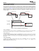
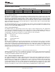
8.4.1.6 Operation in the Active State
In the active state, the DRV2605L device has I
2
C communication and is capable of playing waveforms, running
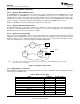
calibration, and running diagnostics. These operations are referred to as processes. Figure 18 shows the flow of
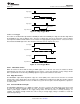
starting, or firing, a process. Notice that the GO signal fires the processes. Note that the GO signal is not the
same as the GO bit. Figure 19 shows a diagram of the GO-signal behavior.
Note: If an output short is present before a waveform is played, changing modes (with the MODE[2:0] bit in register 0x01) is
required to resume normal playback.
Figure 18. Diagram of Active States
8.4.2 Changing Modes of Operation
The DRV2605L has multiple modes for playing waveforms, as well as a calibration mode and a diagnostic mode.
Table 2 lists the available modes.
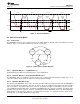
Table 2. Mode Selection Table
MODE MODE[2:0] N_PWM_ANALOG
Internal trigger mode 0 X
External Trigger mode (edge) 1 X
External trigger mode (level) 2 X
Analog input mode 3 0
PWM mode 3 1
Audio-to-vibe mode 4 X
RTP mode 5 X
Diagnostics mode 6 X
Calibration mode 7 X
20 Submit Documentation Feedback Copyright © 2014, Texas Instruments Incorporated
Product Folder Links: DRV2605L