
Data Sheet
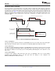

Input and output
Accleration
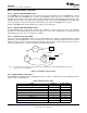
Ideal Open-Loop Waveform for Motor A
Output with feedback
Ideal Open-Loop Waveform for Motor B
Same simple input for
both motors
Feedback provides
optimum output drive
DRV2605L
SLOS854C –MAY 2014–REVISED SEPTEMBER 2014
www.ti.com
Feature Description (continued)
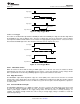
An open-loop haptic system typically drives an overdrive voltage at startup that is higher than the steady-state
rated voltage of the actuator to decrease the startup latency of the actuator. Likewise, a braking algorithm must
be employed for effective braking. When using an open-loop driver, these behaviors must be contained in the
input waveform data. Figure 12 shows how two different ERMs with different startup behaviors (Motor A and
Motor B) can both be driven optimally by the smart-loop architecture with a simple input for both motors. The
smart-loop architecture works equally well for LRAs with a combination of feedback control and an auto-
resonance engine.
Figure 12. Waveform Simplification With Smart Loop
8.3.2.4.1 Startup Boost
To reduce the actuator start-time performance, the DRV2605L device has an overdrive boost feature that applies
higher loop gain to transient response of the actuator. The STARTUP_BOOST bit enables this feature.
8.3.2.4.2 Brake Factor
To reduce the actuator brake-time performance, the DRV2605L device provides a means to increase the gain
ratio between braking and driving gain. Higher feedback-gain ratios reduce the brake time, however, these ratios
also reduce the stability of the closed-loop system. The FB_BRAKE_FACTOR[2:0] bits can be adjusted to set the
brake factor.
8.3.2.4.3 Brake Stabilizer
To improve brake stability at high brake-factor gain ratios, the DRV2605L device has a brake-stabilizer
mechanism that automatically reduces the loop gain when the braking is near completion. The
BRAKE_STABILIZER bit enables this feature.
12 Submit Documentation Feedback Copyright © 2014, Texas Instruments Incorporated
Product Folder Links: DRV2605L