
Data Sheet

9
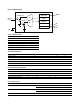
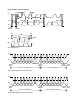
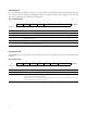
7 6 5 4 3 2 1 0
CMD CLEAR WORD Resv ADDRESS COMMAND
Reset Value: 0 0 0 0 0 0 0 0
Command Register
The command register specifies the address of the target register for subsequent read and write operations. The Send
Byte protocol is used to configure the COMMAND register. The command register contains eight bits as described in
Table 3. The command register defaults to 00h at power on.
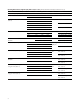
Table 3. Command Register
FIELD BIT DESCRIPTION
CMD 7 Select command register. Must write as 1.
CLEAR 6 Interrupt clear. Clears any pending interrupt. This bit is a write-one-to-clear bit. It is self clearing.
WORD 5 I
2
C Write/Read Word Protocol. 1 indicates that this I
2
C transaction is using either the I
2
C Write Word or
Read Word protocol.
Resv 4 Reserved. Write as 0.
ADDRESS 3:0 Register Address. This field selects the specific control or status register for following write and read
commands according to Table 2.
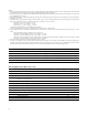
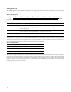
7 6 5 4 3 2 1 0
Oh Resv Resv Resv Resv Resv Resv POWER CONTROL
Reset Value: 0 0 0 0 0 0 0 0
Control Register (0h)
The CONTROL register contains two bits and is primarily used to power the APDS-9301 device up and down as shown
in Table 4.
Table 4. Control Re gister
FIELD BIT DESCRIPTION
Resv 7:2 Reserved. Write as 0.
POWER 1:0 Power up/power down. By writing a 03h to this register, the device is powered up. By writing a 00h to
this register, the device is powered down.
NOTE: If a value of 03h is written, the value returned during a read cycle will be 03h. This feature can be used to
verify that the device is communicating properly.