
Data Sheet

8
Register Set
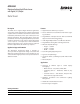
The APDS-9301 is controlled and monitored by sixteen registers (three are reserved) and a command register accessed
through the serial interface. These registers provide for a variety of control functions and can be read to determine
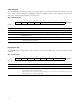
results of the ADC conversions. The register set is summarized in Table 2.
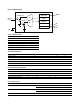
Table 2. Register Address
ADDRESS RESISTER NAME REGISTER FUNCTION
-- COMMAND Specifies register address
0h CONTROL Control of basic functions
1h TIMING Integration time/gain control
2h THRESHLOWLOW Low byte of low interrupt threshold
3h THRESHLOWHIGH High byte of low interrupt threshold
4h THRESHHIGHLOW Low byte of high interrupt threshold
5h THRESHHIGHHIGH High byte of high interrupt threshold
6h INTERRUPT Interrupt control
7h -- Reserved
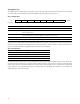
8h CRC Factory test — not a user register
9h -- Reserved
Ah ID Part number/ Rev ID
Bh -- Reserved
Ch DATA0LOW Low byte of ADC channel 0
Dh DATA0HIGH High byte of ADC channel 0
Eh DATA1LOW Low byte of ADC channel 1
Fh DATA1HIGH High byte of ADC channel 1
The mechanics of accessing a specific register depends on the specific I
2
C protocol used. Refer to the section on I
2
C
protocols. In general, the COMMAND register is written first to specify the specific control/status register for following
read/write operations.