
Data Sheet

17
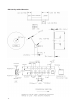
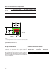
Recommended Reflow Profile
50 100 300150 200 250
t-TIME
(SECONDS)
25
80
120
150
180
200
230
255
0
T - TEMPERATURE (°C)
R1
R2
R3
R4
R5
217
MAX 260C
60 sec to 90 sec
Above 217 C
P1
HEAT
UP
P2
SOLDER PASTE DRY
P3
SOLDER
REFLOW
P4
COOL DOWN
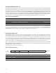
The reflow profile is a straight-line representation of
a nominal temperature profile for a convective reflow
solder process. The temperature profile is divided into
four process zones, each with different ∆T/∆time tem-
perature change rates or duration. The ∆T/∆time rates or
duration are detailed in the above table. The temperatures
are measured at the component to printed circuit board
connections.
In process zone P1, the PC board and component pins are
heated to a temperature of 150°C to activate the flux in the
solder paste. The temperature ramp up rate, R1, is limited
to 3°C per second to allow for even heating of both the PC
board and component pins.
Process zone P2 should be of sufficient time duration (100
to 180 seconds) to dry the solder paste. The temperature
is raised to a level just below the liquidus point of the
solder.
Process zone P3 is the solder reflow zone. In zone P3, the
temperature is quickly raised above the liquidus point
of solder to 260°C (500°F) for optimum results. The dwell
time above the liquidus point of solder should be between
60 and 90 seconds. This is to assure proper coalescing of
the solder paste into liquid solder and the formation of
good solder connections. Beyond the recommended
dwell time the intermetallic growth within the solder con-
nections becomes excessive, resulting in the formation of
weak and unreliable connections. The temperature is then
rapidly reduced to a point below the solidus temperature
of the solder to allow the solder within the connections to
freeze solid.
Process zone P4 is the cool down after solder freeze. The
cool down rate, R5, from the liquidus point of the solder to
25°C (77°F) should not exceed 6°C per second maximum.
This limitation is necessary to allow the PC board and
component pins to change dimensions evenly, putting
minimal stresses on the component.
It is recommended to perform reflow soldering no more
than twice.
Process Zone Symbol ∆T
Maximum ∆T/∆time
or Duration
Heat Up P1, R1 25°C to 150°C 3°C/s
Solder Paste Dry P2, R2 150°C to 200°C 100s to 180s
Solder Reflow P3, R3
P3, R4
200°C to 260°C
260°C to 200°C
3°C/s
-6°C/s
Cool Down P4, R5 200°C to 25°C -6°C/s
Time maintained above liquidus point, 217°C > 217°C 60s to 120s
Peak Temperature 260°C –
Time within 5°C of actual Peak Temperature – 20s to 40s
Time 25°C to Peak Temperature 25°C to 260°C 8mins