
Data Sheet

11
Interrupt Threshold Register (2h - 5h)
The interrupt threshold registers store the values to be used as the high and low trigger points for the comparison function
for interrupt generation. If the value generated by channel 0 crosses below or is equal to the low threshold specified, an
interrupt is asserted on the interrupt pin. If the value generated by channel 0 crosses above the high threshold specified,
an interrupt is asserted on the interrupt pin. Registers THRESHLOWLOW and THRESHLOWHIGH provide the low byte and
high byte, respectively, of the lower interrupt threshold. Registers THRESHHIGHLOW and THRESHHIGHHIGH provide the
low and high bytes, respectively, of the upper interrupt threshold. The high and low bytes from each set of registers are
combined to form a 16–bit threshold value. The interrupt threshold registers default to 00h on power up.
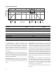
Table 7. Interrupt Threshold Register
REGISTER ADDRESS BITS DESCRIPTION
THRESHLOWLOW 2h 7:0 ADC channel 0 lower byte of the low threshold
THRESHLOWHIGH 3h 7:0 ADC channel 0 upper byte of the low threshold
THRESHHIGHLOW 4h 7:0 ADC channel 0 lower byte of the high threshold
THRESHHIGHHIGH 5h 7:0 ADC channel 0 upper byte of the high threshold
NOTE: Since two 8-bit values are combined for a single 16-bit value for each of the high and low interrupt thresholds, the Send Byte protocol should
not be used to write to these registers. Any values transferred by the Send Byte protocol with the MSB set would be interpreted as the COMMAND field
and stored as an address for subsequent read/write operations and not as the interrupt threshold information as desired. The Write Word protocol
should be used to write byte-paired registers. For example, the THRESHLOWLOW and THRESHLOWHIGH registers (as well as the THRESHHIGHLOW and
THRESHHIGHHIGH registers) can be written together to set the 16–bit ADC value in a single transaction.
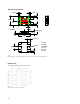
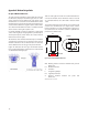
7 6 5 4 3 2 1 0
6h Resv Resv INTR PERSIST INTERRUPT
Reset Value: 0 0 0 0 0 0 0 0
Interrupt Control Register (6h)
The INTERRUPT register controls the extensive interrupt capabilities of the APDS-9301. The APDS-9301 permits tradi-
tional level-style interrupts. The interrupt persist bit field (PERSIST) provides control over when interrupts occur. A value
of 0 causes an interrupt to occur after every integration cycle regardless of the threshold settings. A value of 1 results
in an interrupt after one integration time period outside the threshold window. A value of N (where N is 2 through 15)
results in an interrupt only if the value remains outside the threshold window for N consecutive integration cycles. For
example, if N is equal to 10 and the integration time is 402 ms, then the total time is approximately 4 seconds.
When a level Interrupt is selected, an interrupt is generated whenever the last conversion results in a value outside
of the programmed threshold window. The interrupt is active-low and remains asserted until cleared by writing the
COMMAND register with the CLEAR bit set.
NOTE: Interrupts are based on the value of Channel 0 only.
Table 8. Interrupt Control Register
FIELD BITS DESCRIPTION
Resv 7:6 Reserved. Write as 0.
INTR 5:4 INTR Control Select. This field determines mode of interrupt logic according to Table 9, below.
PERSIST 3:0 Interrupt persistence. Controls rate of interrupts to the host processor as shown in Table 10, below.