
Data Sheet

Final Datasheet
BME280 Environmental sensor
Page 8
BST-BME280-DS001-10 | Revision 1.1 | May 2015 Bosch Sensortec
© Bosch Sensortec GmbH reserves all rights even in the event of industrial property rights. We reserve all rights of disposal such as copying and passing on to
third parties. BOSCH and the symbol are registered trademarks of Robert Bosch GmbH, Germany.
Note: Specifications within this document are subject to change without notice.
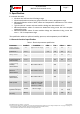
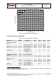
1.2 Humidity parameter specification
2
Table 2: Humidity parameter specification
Parameter
Symbol
Condition
Min
Typ
Max
Unit
Operating range
3
R
H
For temperatures
< 0 °C and > 60 °C
see Figure 1
-40
25
85
°C
0
100
%RH
Supply current
I
DD,H
1 Hz forced mode,
humidity and
temperature
1.8
2.8
µA
Absolute accuracy
tolerance
A
H
2080 %RH,
25 °C, including
hysteresis
1.3
±3
1.4
%RH
Hysteresis
4
H
H
109010 %RH,
25 °C
1.5
±1
%RH
Nonlinearity
5
NL
H
1090 %RH, 25 °C
1
%RH
Response time to
complete 63% of step
6
900 or 090 %RH,
25°C
1
s
Resolution
R
H
0.008
%RH
Noise in humidity (RMS)
N
H
Highest oversampling,
see chapter 3.6
0.02
%RH
Long term stability
H
stab
1090 %RH, 25 °C
0.5
%RH/
year
2
Target values
3
When exceeding the operating range (e.g. for soldering), humidity sensing performance is
temporarily degraded and reconditioning is recommended as described in section 7.8.
Operating range only for non-condensing environment.
4
For hysteresis measurement the sequence 103050709070503010 %RH is
used. The hysteresis is defined as the difference between measurements of the humidity up /
down branch and the averaged curve of both branches
5
Non-linear contributions to the sensor data are corrected during the calculation of the relative
humidity by the compensation formulas described in section 4.2.3.
6
The air-flow in direction to the vent-hole of the device has to be dimensioned in a way that a
sufficient air exchange inside to outside will be possible. To observe effects on the response
time-scale of the device an air-flow velocity of approx. 1 m/s is needed.