
Data Sheet

Final Datasheet
BME280 Environmental sensor
Page 38
BST-BME280-DS001-10 | Revision 1.1 | May 2015 Bosch Sensortec
© Bosch Sensortec GmbH reserves all rights even in the event of industrial property rights. We reserve all rights of disposal such as copying and passing on to
third parties. BOSCH and the symbol are registered trademarks of Robert Bosch GmbH, Germany.
Note: Specifications within this document are subject to change without notice.
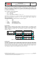
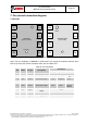
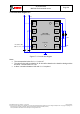
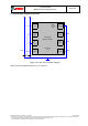
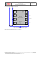
7.2 Connection diagram I
2
C
I2C address bit 0
GND: '0'; V
DDIO
: '1'
TOP VIEW
(pads not visible)
8
V
DD
7
GND
6
V
DDIO
5
SDO
C
1
V
DDIO
V
DD
C
2
1
GND
2
CSB
3
SDI
4
SCK
SDA
SCL
Vent hole
R
2
R
1
Figure 17: I²C connection diagram
Notes:
The recommended value for C
1
, C
2
is 100 nF
The value for the pull-up resistors R
1
, R
2
should be based on the interface timing and the
bus load; a normal value is 4.7 kΩ
A direct connection between CSB and V
DDIO
is required