
Data Sheet

Final Datasheet
BME280 Environmental sensor
Page 31
BST-BME280-DS001-10 | Revision 1.1 | May 2015 Bosch Sensortec
© Bosch Sensortec GmbH reserves all rights even in the event of industrial property rights. We reserve all rights of disposal such as copying and passing on to
third parties. BOSCH and the symbol are registered trademarks of Robert Bosch GmbH, Germany.
Note: Specifications within this document are subject to change without notice.
The 7-bit device address is 111011x. The 6 MSB bits are fixed. The last bit is changeable by
SDO value and can be changed during operation. Connecting SDO to GND results in slave
address 1110110 (0x76); connection it to V
DDIO
results in slave address 1110111 (0x77), which
is the same as BMP280. The SDO pin cannot be left floating; if left floating, the
I²C address will be undefined.
The I²C interface uses the following pins:
SCK: serial clock (SCL)
SDI: data (SDA)
SDO: Slave
DDIO
CSB must be connected to V
DDIO
to select I²C interface. SDI is bi-directional with open drain to
GND: it must be externally connected to V
DDIO
via a pull up resistor. Refer to chapter 7 for
connection instructions.
The following abbreviations will be used in the I²C protocol figures:
S Start
P Stop
ACKS Acknowledge by slave
ACKM Acknowledge by master
NACKM Not acknowledge by master
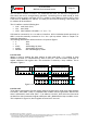
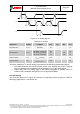
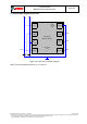
6.2.1 I²C write
Writing is done by sending the slave address , resulting in slave
address 111011X X . Then the master sends pairs of
register addresses and register data. The transaction is ended by a stop condition. This is
depicted in Figure 9.
Start RW ACKS ACKS ACKS
1 1 1 0 1 1 X 0 1 0 1 0 0 0 0 0 bit7 bit6 bit5 bit4 bit3 bit2 bit1 bit0
…
ACKS ACKS Stop
…
1 0 1 0 0 0 0 1 bit7 bit6 bit5 bit4 bit3 bit2 bit1 bit0
Register data - address A0h
Register address (A0h)
Register address (A1h)
S
Slave Address
Control byte
Data byte
Control byte
Data byte
P
Register data - address A1h
Figure 9: I²C multiple byte write (not auto-incremented)
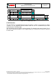
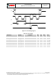
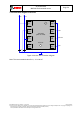
6.2.2 I²C read
To be able to read registers, first the register address must be sent in write mode (slave address
111011X0). Then either a stop or a repeated start condition must be generated. After this the
slave is addre
out data from auto-incremented register addresses until a NOACKM and stop condition occurs.
This is depicted in Figure 10, where register 0xF6 and 0xF7 are read.