
Data Sheet

Final Datasheet
BME280 Environmental sensor
Page 14
BST-BME280-DS001-10 | Revision 1.1 | May 2015 Bosch Sensortec
© Bosch Sensortec GmbH reserves all rights even in the event of industrial property rights. We reserve all rights of disposal such as copying and passing on to
third parties. BOSCH and the symbol are registered trademarks of Robert Bosch GmbH, Germany.
Note: Specifications within this document are subject to change without notice.
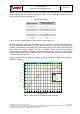
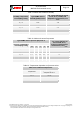
Measurement H
time
current
I
DDSL
I
DDSB
I
DDP
I
DDH
POR Mode[1:0] = 11
Measurement P
Measurement T
Data readout
when needed
Write
settings
t
standby
I
DDT
Measurement H
Measurement P
Measurement T
t
measure
cycle time = t
measure
+ t
standby
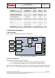
Figure 5: Normal mode timing diagram
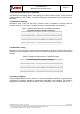
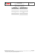
3.4 Measurement flow
The BME280 measurement period consists of a temperature, pressure and humidity
measurement with selectable oversampling. After the measurement period, the pressure and
temperature data can be passed through an optional IIR filter, which removes short-term
fluctuations in pressure (e.g. caused by slamming a door). For humidity, such a filter is not
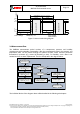
needed and has not been implemented. The flow is depicted in the diagram below.
Measure temperature
(oversampling set by osrs_t;
skip if osrs_t = 0)
Start
measurement cycle
Measure pressure
(oversampling set by osrs_p;
skip if osrs_p = 0)
IIR filter enabled?
End
measurement cycle
IIR filter initialised?
Copy ADC values
to filter memory
(initalises IIR filter)
No
Update filter memory using
filter memory, ADC value
and filter coefficient
No
Yes
Yes
Copy filter memory
to output registers
Measure humidity
(oversampling set by osrs_h;
skip if osrs_h = 0)
Figure 6: BME280 measurement cycle
The individual blocks of the diagram above will be detailed in the following subchapters.