
Data Sheet

Final Datasheet
BME280 Environmental sensor
Page 12
BST-BME280-DS001-10 | Revision 1.1 | May 2015 Bosch Sensortec
© Bosch Sensortec GmbH reserves all rights even in the event of industrial property rights. We reserve all rights of disposal such as copying and passing on to
third parties. BOSCH and the symbol are registered trademarks of Robert Bosch GmbH, Germany.
Note: Specifications within this document are subject to change without notice.
of raising the V
DD
and V
DDIO
levels. After powering up, the sensor settles in sleep mode
(described in chapter 3.3.2).
It is prohibited to keep any interface pin (SDI, SDO, SCK or CSB) at a logical high level when
V
DDIO
is switched off. Such a configuration can permanently damage the device due an
excessive current flow through the ESD protection diodes.
If V
DDIO
is supplied, but V
DD
is not, the interface pins are kept at a high-Z level. The bus can
therefore already be used freely before the BME280 V
DD
supply is established.
Resetting the sensor is possible by cycling V
DD
level or by writing a soft reset command. Cycling
the V
DDIO
level will not cause a reset.
3.3 Sensor modes
The BME280 offers three sensor modes: sleep mode, forced mode and normal mode. These
can be selected using the mode[1:0] setting (see chapter 5.4.5). The available modes are:
Sleep mode: no operation, all registers accessible, lowest power, selected after startup
Forced mode: perform one measurement, store results and return to sleep mode
Normal mode: perpetual cycling of measurements and inactive periods.
The modes will be explained in detail in chapters 3.3.2 (sleep mode), 3.3.3 (forced mode) and
3.3.4 (normal mode).
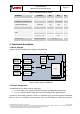
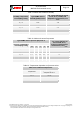
3.3.1 Sensor mode transitions
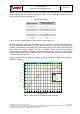
The supported mode transitions are shown in Figure 3. If the device is currently performing a
measurement, execution of mode switching commands is delayed until the end of the currently
running measurement period. Further mode change commands or other write commands to the
register ctrl_hum are ignored until the mode change command has been executed. Mode
transitions other than the ones shown below are tested for stability but do not represent
recommended use of the device.
Power OFF
(V
DD
or V
DDIO
= 0)
V
DD
and V
DDIO
supplied
Mode
[
1
:
0
] =
00
Mode[
1
:
0
] =
01
Sleep
Normal
(cyclic standby and
measurement periods)
Mode
[
1
:
0
] =
11
Forced
(one measurement
period)
Mode[1:0] = 01
Figure 3: Sensor mode transition diagram