
Data Sheet

Page 24 ams Datasheet
Document Feedback [v1-00] 2016-Dec-23
CCS811 − Bootloader Register Overview
All I²C transactions must use the (7bits) slave address 0x5A or
0x5B depending on status of ADDR pin when writing to and
reading from the CCS811. Figure 23 shows the bootloader
register map for CCS811.
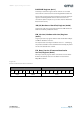
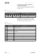
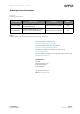
Figure 23:
CCS811 Bootloader Register Map
Note(s):
1. The number of bytes read from a register must not exceed the size in this table.
2. For more information on performing application code download please refer to application note ams AN000371.
Address Register R/W Size Description
0x00 STATUS R 1 byte Status register
0x20 HW_ID R 1 byte Hardware ID. The value is 0x81
0x21 HW Version R 1 byte Hardware Version. The value is 0x1X
0x23 FW_Boot_Version R 2 bytes
Firmware Boot Version. The first 2 bytes contain the
firmware version number for the boot code.
0x24 FW_App_Version R 2 bytes
Firmware Application Version. The first 2 bytes contain
the firmware version number for the application code.
0xE0 ERROR_ID R 1 byte
Error ID. When the status register reports an error it
source is located in this register
0xF1 APP_ERASE W 4 bytes
If the correct 4 bytes (0xE7 0xA7 0xE6 0x09) are written
to this register in a single sequence the device will start
the application erase
0xF2 APP_DATA W 9 bytes
Transmit flash code for the bootloader to write to the
application flash code space.
0xF3 APP_VERIFY W -
Starts the process of the bootloader checking though
the application to make sure a full image is valid.
0xF4 APP_START W -
Application start. Used to transition the CCS811 state
from boot to application mode, a write with no data is
required. Before performing a write to APP_START the
Status register should be accessed to check if there is a
valid application present.
0xFF SW_RESET W 4 bytes
If the correct 4 bytes (0x11 0xE5 0x72 0x8A) are written
to this register in a single sequence the device will reset
and return to BOOT mode.
Bootloader Register Overview