
Data Sheet

Page 20 ams Datasheet
Document Feedback [v1-00] 2016-Dec-23
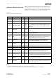
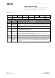
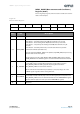
CCS 811 − Application Register Overview
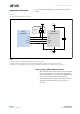
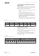
NTC Register (0x06)
Four byte read only register which contains the voltage across
resistor (R
REF
) and the voltage across the NTC resistor from
which the ambient temperature can be determined.
The resistance of the NTC resistor can be determined by the
ratio value and knowledge of the reference resistor used.
R
NTC
= V
NTC
x R
REF
/ V
REF
. The temperature can be determined
from the resistance of the NTC resistor from the datasheet of
the NTC resistor used.
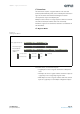
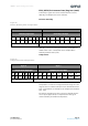
Figure 18:
NTC Register Byte Order
This enables the host to calculate the ambient temperature and
this information can be written to CCS811 to compensate for
temperature changes.
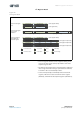
THRESHOLDS Register (0x10)
If ‘interrupt on threshold change’ has been set in the Mode
register (see above), the values in this multi- byte write only
register are used to determine the thresholds and the level of
hysteresis desired.
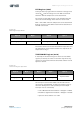
Figure 19:
Thresholds Register Byte Order
An interrupt is asserted if the eCO
2
value moved from the
current range (Low, Medium, or High) into another range by
more than the Hysteresis value (used to prevent multiple
interrupts close to a threshold).
• Low to Medium Threshold default = 1500ppm = 0x05DC
• Medium to High Threshold default = 2500ppm = 0x09C4
• Hysteresis value default = 50 = 0x32
Byte 0 Byte 1 Byte 2 Byte 3
Voltage across R
REF
(mV) Voltage across R
NTC
(mV)
High Byte Low Byte High Byte Low Byte
Byte 0 Byte 1 Byte 2 Byte 3 Byte 4
Low to Medium Threshold Medium to High Threshold
Hysteresis Value
High Byte Low Byte High Byte Low Byte