
Data Sheet

ams Datasheet Page 17
[v1-00] 2016-Dec-23 Document Feedback
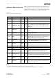
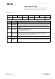
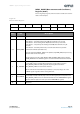
CCS811 − Application Register Overview
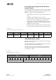
MEAS_MODE (Measurement and Conditions)
Register (0x01)
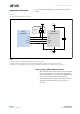
This is Single byte register, which is used to enable sensor drive
mode and interrupts.
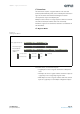
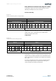
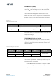
Figure 13:
Measure Mode Register
765 4 3 210
- DRIVE_MODE INTERRUPT THRESH -
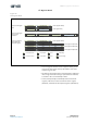
Bit(s) Field Description
7 - Reserved – write ‘0’
6:4 DRIVE_MODE
000: Mode 0 – Idle (Measurements are disabled in this mode)
001: Mode 1 – Constant power mode, IAQ measurement every second
010: Mode 2 – Pulse heating mode IAQ measurement every 10 seconds
011: Mode 3 – Low power pulse heating mode IAQ measurement every 60
seconds
100: Mode 4 – Constant power mode, sensor measurement every 250ms
1xx: Reserved modes (For future use)
In mode 4, the ALG_RESULT_DATA is not updated, only RAW_DATA; the processing
must be done on the host system.
A new sample is placed in ALG_RESULT_DATA and RAW_DATA registers and the
DATA_READY bit in the STATUS register is set at the defined measurement interval.
3INT_DATARDY
0: Interrupt generation is disabled
1: The nINT signal is asserted (driven low) when a new sample is ready in
ALG_RESULT_DATA. The nINT signal will stop being driven low when
ALG_RESULT_DATA is read on the I²C interface.
At the end of each measurement cycle (250ms, 1s, 10s, 60s) a flag is set in the
STATUS register regardless of the setting of this bit..
2INT_THRESH
0: Interrupt mode (if enabled) operates normally
1: Interrupt mode (if enabled) only asserts the nINT signal (driven low) if the new
ALG_RESULT_DATA crosses one of the thresholds set in the THRESHOLDS register
by more than the hysteresis value (also in the THRESHOLDS register)
1:0 - Reserved