
Data Sheet

RFD77402 DATASHEET v1.8
© 2017 RF Digital Corporation 7.24.2017
www.simblee.com
16
Simblee™ RFD77402
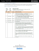
2.2.1 Standby / Leakage in Different Electrical Conditions
Table 5: I
2
C SCL/SCA Power-up/down Sequence
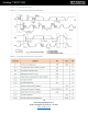
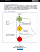
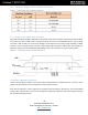
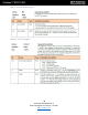
2.2.2 Power-up and power-down Sequence
Figure 14 below shows the RFD77402 power up and power down sequence. Please note that the module itself has
no restrictions in terms of VDD and VI
2
C_pull-up sequencing, but in the case of VDD ON while VI
2
C_pull-up supply
unit offers a path to GND. The value of such leakage current depends on the power supply impedance to GND.
Therefore, unless the power supply unit offers a significantly high impedance to GND limiting such leakage, the
application designer should avoid keeping VDD ON while VI
2
C_pull-up Is OFF for a long time (steady state).
Figure 14: I
2
C SCL/SDA Power-up/down Sequence
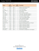
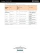
2.3 Module Programming Interface
The I
2
C Interface registers defined in this section remain powered when in standby mode. For this reason, these
registers are accessible at any time through the I
2
C direct address scheme.
Note that the addresses of these registers are provided as 16-bit addresses according to the internal MCPU
memory map. The external user must use the least significant byte of the address to access these registers through
the I
2
C direct addressing scheme.