
Data Sheet
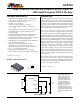
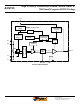


High Accuracy, Galvanically Isolated Current Sensor IC
With Small Footprint SOIC8 Package
ACS723
6
Allegro MicroSystems, LLC
115 Northeast Cutoff
Worcester, Massachusetts 01615-0036 U.S.A.
1.508.853.5000; www.allegromicro.com
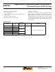
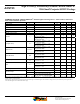
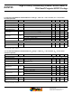
COMMON ELECTRICAL CHARACTERISTICS
1:
Valid through the full range of T
A
= –40°C to 150°C
, and at V
CC
=
5.0 V; unless otherwise specif ied
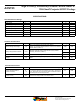
Characteristic Symbol Test Conditions Min. Typ. Max. Units
Supply Voltage V
CC
4.5 5 5.5 V
Supply Current I
CC
V
CC
within V
CC
(min) and V
CC
(max) – 9 14 mA
Output Capacitance Load C
L
VIOUT to GND – – 10 nF
Output Resistive Load R
L
VIOUT to GND 4.7 – – kΩ
Primary Conductor Resistance R
IP
T
A
= 25°C – 0.65 – mΩ
Magnetic Coupling Factor C
F
– 10 – G/A
Rise Time t
r
I
P
= I
P
(max), T
A
= 25°C, C
L
= 1 nF,
BW_SEL tied to GND
– 4 – μs
I
P
= I
P
(max), T
A
= 25°C, C
L
= 1 nF,
BW_SEL tied to VCC
– 17.5 – μs
Propagation Delay t
pd
I
P
= I
P
(max), T
A
= 25°C, C
L
= 1 nF,
BW_SEL tied to GND
– 1 – μs
I
P
= I
P
(max), T
A
= 25°C, C
L
= 1 nF,
BW_SEL tied to VCC
– 5 – μs
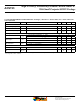
Response Time t
RESPONSE
I
P
= I
P
(max), T
A
= 25°C, C
L
= 1 nF,
BW_SEL tied to GND
– 5 – μs
I
P
= I
P
(max), T
A
= 25°C, C
L
= 1 nF,
BW_SEL tied to VCC
– 22.5 – μs
Internal Bandwidth BWi
Small signal –3 dB; C
L
= 1 nF,
BW_SEL tied to GND
– 80 – kHz
Small signal –3 dB; C
L
= 1nF,
BW_SEL tied to VCC
– 20 – kHz
Noise Density I
ND
Input referenced noise density;
T
A
= 25°C, C
L
= 1 nF
– 110 –
µA
(rms)
/
√Hz
Noise I
N
Input referenced noise; BWi = 80 kHz,
T
A
= 25°C, C
L
= 1 nF
– 30 – mA
(rms)
Input referenced noise; BWi = 20 kHz,
T
A
= 25°C, C
L
= 1 nF
– 15 – mA
(rms)
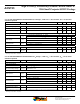
Nonlinearity E
LIN
Through full range of I
PR
– ±1 – %
Saturation Voltage
2
V
OH
R
L
= 4.7 kΩ, T
A
= 25°C V
CC
– 0.5 – – V
V
OL
R
L
= 4.7 kΩ, T
A
= 25°C – – 0.5 V
Power-On Time t
PO
Output reaches 90% of steady-state
level, T
A
= 25°C, I
P
= I
PR
(max) applied
– 64 – μs
1
Device may be operated at higher primary current levels, I
P
, ambient temperatures, T
A
, and internal leadframe temperatures, provided the Maximum Junction Tem-
perature, T
J
(max), is not exceeded.
2
The sensor IC will continue to respond to current beyond the range of I
P
until the high or low saturation voltage; however, the nonlinearity in this region will be
worse than through the rest of the measurement range.