
Data Sheet

High Accuracy, Galvanically Isolated Current Sensor IC
With Small Footprint SOIC8 Package
ACS723
18
Allegro MicroSystems, LLC
115 Northeast Cutoff
Worcester, Massachusetts 01615-0036 U.S.A.
1.508.853.5000; www.allegromicro.com
Sensitivity (Sens)
The change in sensor IC output in response to a 1 A change
through the primary conductor. The sensitivity is the product of
the magnetic circuit sensitivity (G / A) (1 G = 0.1 mT)and the
linear IC amplifier gain (mV/G). The linear IC amplifier gain is
programmed at the factory to optimize the sensitivity (mV/A) for
the full-scale current of the device.
Nonlinearity (E
LIN
)
The nonlinearity is a measure of how linear the output of the sen-
sor IC is over the full current measurement range. The nonlinear-
ity is calculated as:
1–
[{
[{
V
IOUT
(I
PR
(max))
– V
IOUT(Q)
× 100 (%)
E
LIN
=
2 × V
IOUT
(I
PR
(max)/2)
– V
IOUT(Q)
where V
IOUT
(I
PR
(max)) is the output of the sensor IC with the
maximum measurement current flowing through it and
V
IOUT
(I
PR
(max)/2) is the output of the sensor IC with half of the
maximum measurement current flowing through it.
Zero Current Output Voltage (V
IOUT(Q)
)
The output of the sensor when the primary current is zero. For
a unipolar supply voltage, it
nominally remains at 0.5 × V
CC
for
a bidirectional device and 0.1 × V
CC
for a unidirectional device.
For example, in the case of a bidirectional output device, V
CC
=
5.0 V translates into V
IOUT(Q)
= 2.5 V. Variation in V
IOUT(Q)
can
be attributed to the resolution of the Allegro linear IC quiescent
voltage trim and thermal drift.
Offset Voltage (V
OE
)
The deviation of the device output from its ideal quiescent value
of 0.5 × V
CC
(bidirectional) or 0.1 × V
CC
(unidirectional) due to
nonmagnetic causes. To convert this voltage to amperes, divide
by the device sensitivity, Sens.
Total Output Error (E
TOT
)
The difference between the current measurement from the sensor
IC and the actual current (I
P
), relative to the actual current. This
is equivalent to the difference between the ideal output voltage
and the actual output voltage, divided by the ideal sensitivity,
relative to the current flowing through the primary conduction
path:
E
TOT
(I
P
)
V
IOUT_ideal
(I
P
) – V
IOUT
(I
P
)
Sens
ideal
(I
P
)
×
I
P
×
100 (%)=
The Total Output Error incorporates all sources of error and is a
function of I
P
. At relatively high currents, E
TOT
will be mostly
DEFINITIONS OF ACCURACY CHARACTERISTICS
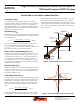
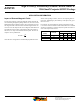
Figure 1. Output voltage versus sensed current
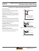
Figure 2. Total Output Error versus sensed current
0 A
Decreasing
V
IOUT
(V)
Accuracy Across
Temperature
Accuracy Across
Temperature
Accuracy Across
Temperature
Accuracy at
25°C Only
Accuracy at
25°C Only
Accuracy at
25°C Only
Increasing
V
IOUT
(V)
Ideal V
IOUT
I
PR
(min)
I
PR
(max)
+I
P
(A)
–I
P
(A)
V
IOUT(Q)
Full Scale I
P
+I
P
–I
P
+E
TOT
–E
TOT
Across Temperature
25°C Only
due to sensitivity error, and at relatively low currents, E
TOT
will
be mostly due to Offset Voltage (V
OE
). In fact, at I
P
= 0, E
TOT
approaches infinity due to the offset. This is illustrated in figures
1 and 2. Figure 1 shows a distribution of output voltages versus I
P
at 25°C and across temperature. Figure 2 shows the correspond-
ing E
TOT
versus I
P
.