
Data Sheet

Magnetometer register description LSM9DS1
64/72 DocID025715 Rev 2
8.6 CTRL_REG2_M (21h)
8.7 CTRL_REG3_M (22h)
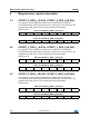
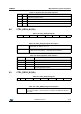
Table 112. CTRL_REG2_M register
0
(1)
1. These bits must be set to ‘0’ for the correct operation of the device.
FS1 FS0 0
(1)
REBOOT SOFT_RST 0
(1)
0
(1)
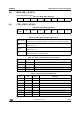
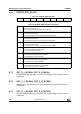
Table 113. CTRL_REG2_M register description
FS[1:0] Full-scale configuration. Default value: 00
Refer to Table 114
REBOOT
Reboot memory content. Default value: 0
(0: normal mode; 1: reboot memory content)
SOFT_RST
Configuration registers and user register reset function.
(0: default value; 1: reset operation)
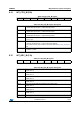
Table 114. Full-scale selection
FS1 FS0 Full scale
0 0 ± 4 gauss
0 1 ± 8 gauss
1 0 ± 12 gauss
1 1 ± 16 gauss
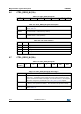
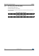
Table 115. CTRL_REG3_M register
I2C_
DISABLE
0
(1)
1. These bits must be set to ‘0’ for the correct operation of the device.
LP 0
(1)
0
(1)
SIM MD1 MD0
Table 116. CTRL_REG3_M register description
I2C_DISABLE Disable I
2
C interface. Default value 0. (0: I
2
C enable; 1: I
2
C disable)
LP Low-power mode configuration. Default value: 0
If this bit is ‘1’, the DO[2:0] is set to 0.625 Hz and the system performs, for each
channel, the minimum number of averages. Once the bit is set to ‘0’, the magnetic
data rate is configured by the DO bits in the CTRL_REG1_M (20h) register.
SIM SPI Serial Interface mode selection. Default value: 0
(0: SPI only write operations enabled; 1: SPI read and write operations enable).
MD[1:0] Operating mode selection. Default value: 11
Refer to Table 117.