
Data Sheet

Accelerometer and gyroscope register description LSM9DS1
48/72 DocID025715 Rev 2
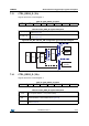
7.15 ORIENT_CFG_G (13h)
Angular rate sensor sign and orientation register.
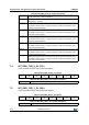
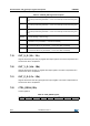
Table 53. ORIENT_CFG_G register
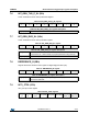
Table 54. ORIENT_CFG_G register description
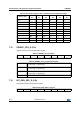
7.16 INT_GEN_SRC_G (14h)
Angular rate sensor interrupt source register.
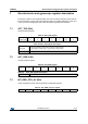
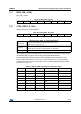
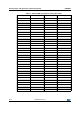
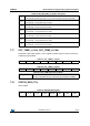
Table 52. Gyroscope high-pass filter cutoff frequency configuration [Hz]
(1)
1. Values in the table are indicative and can vary proportionally with the specific ODR value.
HPCF_G [3:0]
ODR= 14.9
Hz
ODR= 59.5
Hz
ODR= 119
Hz
ODR= 238
Hz
ODR= 476
Hz
ODR= 952
Hz
0000 148153057
0001 0.5 2481530
0010 0.2 124815
0011 0.10.51248
0100 0.05 0.2 0.5 1 2 4
0101 0.02 0.1 0.2 0.5 1 2
0110 0.01 0.05 0.1 0.2 0.5 1
0111 0.005 0.02 0.05 0.1 0.2 0.5
1000 0.002 0.01 0.02 0.05 0.1 0.2
1001 0.001 0.005 0.01 0.02 0.05 0.1
0
(1)
1. These bits must be set to ‘0’ for the correct operation of the device.
0
(1)
SignX_G SignY_G SignZ_G Orient_2 Orient_1 Orient_0
SignX_G Pitch axis (X) angular rate sign. Default value: 0
(0: positive sign; 1: negative sign)
SignY_G Roll axis (Y) angular rate sign. Default value: 0
(0: positive sign; 1: negative sign)
SignZ_G Yaw axis (Z) angular rate sign. Default value: 0
(0: positive sign; 1: negative sign)
Orient [2:0] Directional user orientation selection. Default value: 000
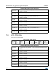
Table 55. INT_GEN_SRC_G register
0 IA_G ZH_G ZL_G YH_G YL_G XH_G XL_G