
Data Sheet

DocID025715 Rev 2 45/72
LSM9DS1 Accelerometer and gyroscope register description
72
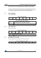
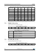
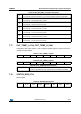
7.11 WHO_AM_I (0Fh)
Who_AM_I register.
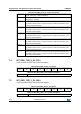
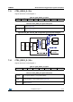
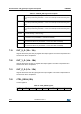
7.12 CTRL_REG1_G (10h)
Angular rate sensor Control Register 1.
Table 44. CTRL_REG1_G register
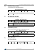
Table 45. CTRL_REG1_G register description
ODR_G [2:0] are used to set ODR selection when both the accelerometer and gyroscope
are activated. BW_G [1:0] are used to set gyroscope bandwidth selection.
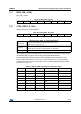
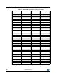
The following table summarizes all frequencies available for each combination of the
ODR_G / BW_G bits after LPF1 (see Table 46) and LPF2 (see Table 47) when both the
accelerometer and gyroscope are activated. For more details regarding signal processing
please refer to Figure 28.
Table 43. WHO_AM_I register
01101000
ODR_G2 ODR_G1 ODR_G0 FS_G1 FS_G0 0
(1)
1. This bit must be set to ‘0’ for the correct operation of the device.
BW_G1 BW_G0
ODR_G [2:0]
Gyroscope output data rate selection. Default value: 000
(Refer to Table 46 and Table 47)
FS_G [1:0]
Gyroscope full-scale selection. Default value: 00
(00: 245 dps; 01: 500 dps; 10: Not Available; 11: 2000 dps)
BW_G [1:0] Gyroscope bandwidth selection. Default value: 00
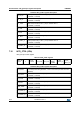
Table 46. ODR and BW configuration setting (after LPF1)
ODR_G2 ODR_G1 ODR_G0 ODR [Hz] Cutoff [Hz]
(1)
1. Values in the table are indicative and can vary proportionally with the specific ODR value.
0 0 0 Power-down n.a.
0 0 1 14.9 5
0 1 0 59.5 19
0 1 1 119 38
1 0 0 238 76
1 0 1 476 100
1 1 0 952 100
1 1 1 n.a. n.a.