
Data Sheet

Digital interfaces LSM9DS1
30/72 DocID025715 Rev 2
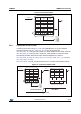
some other function, it can hold the clock line, SCL low to force the transmitter into a wait
state. Data transfer only continues when the receiver is ready for another byte and releases
the data line. If a slave receiver doesn’t acknowledge the slave address (i.e. it is not able to
receive because it is performing some real-time function) the data line must be left high by
the slave. The master can then abort the transfer. A low-to-high transition on the SDA line
while the SCL line is high is defined as a STOP condition. Each data transfer must be
terminated by the generation of a STOP (SP) condition.
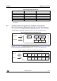
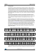
In the presented communication format MAK is Master acknowledge and NMAK is No
Master Acknowledge.
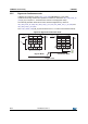
Default address:
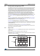
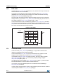
The slave address is completed with a Read/Write bit. If the bit was ‘1’ (Read), a repeated
START (SR) condition must be issued after the two sub-address bytes. If the bit is ‘0’ (Write)
the master will transmit to the slave with direction unchanged. Table 19 and Table 20
explain how the SAD+Read/Write bit pattern is composed, listing all the possible
configurations.
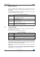
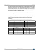
Table 19. Accelerometer and gyroscope SAD+Read/Write patterns
Table 20. Magnetic sensor SAD+Read/Write patterns
Command SAD[6:1] SAD[0] = SA0 R/W SAD+R/W
Read 110101 0 1 11010101 (D5h)
Write 110101 0 0 11010100 (D4h)
Read 110101 1 1 11010111 (D7h)
Write 110101 1 0 11010110 (D6h)
Command SAD[6:2] SAD[1] = SDO/SA1 SAD[0] R/W SAD+R/W
Read 00111 0 0 1 00111001 (39h)
Write 00111 0 0 0 00111000 (38h)
Read 00111 1 0 1 00111101 (3Dh)
Write 00111 1 0 0 00111100 (3Ch)