
Data Sheet

DocID025715 Rev 2 27/72
LSM9DS1 Application hints
72
4 Application hints
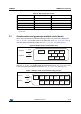
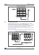
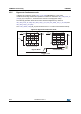
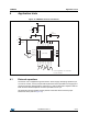
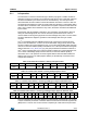
Figure 15. LSM9DS1 electrical connections
4.1 External capacitors
The device core is supplied through the Vdd line. Power supply decoupling capacitors (C2,
C3=100 nF ceramic, C4=10 μF Al) should be placed as near as possible to the supply pin of
the device (common design practice). Capacitor C1 (100 nF) should be a capacitor with low
ESR value and should be placed as near as possible to the C1 pin.
All voltage and ground supplies must be present at the same time to achieve proper
behavior of the IC (refer to Figure 15).
RES
GND
GND
CAP
VDD
VDD
C1
VDD_IO
RES
RES
RES
RES
(TOP VIEW)
1
316
18
DEN_A/G
INT2_A/G
INT1_A/G
INT_M
DRDY_M
CS_M
CS_A/G
SDO_M
SCL/SPC
VDD_IO
SDA/SDI/SDO
SDO_A/G
10nF(16V)
*C5
100 nF
GND
GND
10 μF
C3 C4
Vdd
Vdd_IO
GND
100 nF
C2
GND
GND
* C5 must guarantee 1 nF value unde
r
11 V bias condition
GND
100 nF
C1