
Data Sheet

DocID025715 Rev 2 11/72
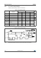
LSM9DS1 Pin description
72
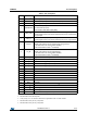
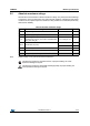
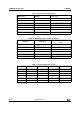
Table 2. Pin description
Pin # Name Function
1 VDDIO
(1)
1. Recommended 100 nF filter capacitor.
Power supply for I/O pins
2 SCL/SPC I
2
C serial clock (SCL) / SPI serial port clock (SPC)
3 VDDIO
(2)
2. Recommended 100 nF filter capacitor.
Power supply for I/O pins
4 SDA/SDI/SDO
I
2
C serial data (SDA)
SPI serial data input (SDI)
3-wire interface serial data output (SDO)
5 SDO_A/G
SPI serial data output (SDO) for the accelerometer and gyroscope
I
2
C least significant bit of the device address (SA0) for the accelerometer
and gyroscope
6 SDO_M
SPI serial data output (SDO) for the magnetometer
I
2
C least significant bit of the device address (SA0) for the magnetometer
7 CS_A/G
SPI enable
I
2
C/SPI mode selection for the accelerometer and gyroscope
(1: SPI idle mode / I
2
C communication enabled;
0: SPI communication mode / I
2
C disabled)
8 CS_M
SPI enable
I
2
C/SPI mode selection for the magnetometer
(1: SPI idle mode / I
2
C communication enabled;
0: SPI communication mode / I
2
C disabled)
9 DRDY_M Magnetic sensor data ready
10 INT_M Magnetic sensor interrupt
11 INT1_A/G Accelerometer and gyroscope interrupt 1
12 INT2_A/G Accelerometer and gyroscope interrupt 2
13 DEN_A/G Accelerometer and gyroscope data enable
14 RES Reserved. Connected to GND.
15 RES Reserved. Connected to GND.
16 RES Reserved. Connected to GND.
17 RES Reserved. Connected to GND.
18 RES Reserved. Connected to GND.
19 GND 0 V supply
20 GND 0 V supply
21 CAP Connected to GND with ceramic capacitor
(3)
3. 10 nF (±10%), 16 V. 1 nF minimum value has to be guaranteed under 11 V bias condition.
22 VDD
(4)
4. Recommended 100 nF plus 10 μF capacitors.
Power supply
23 VDD
(5)
5. Recommended 100 nF plus 10 μF capacitors.
Power supply
24 C1 Capacitor connection (C1 = 100 nF)