
Design Guide

Hardware Interfaces
A DIVISION OF TRIMBLE
28 Hardware Overview
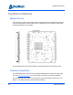
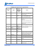
a 3.3 volt logic CMOS input and is internally pulled down with a resistance value of
between 20 and 60 kOhms (40 kOhms nominal). Lines configured as inputs must be low
whenever the module is turned off and low at the time the module is turned on.
GPIOs may be reconfigured individually after power up to become outputs. Lines
configured as outputs consume no excess power if the output is left open.
Configuring GPIO Settings
The GPIO lines are configured as inputs or outputs through the MercuryAPI by setting the
reader configuration parameters /reader/gpio/inputList and /reader/gpio/outputList. The
state of the lines can be Get or Set using the gpiGet() and gpoSet() methods,
respectively. See the language specific reference guide for more details.
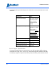
ENABLE Line
CAUTION!
!
!
The polarity of the ENABLE line is opposite from the 4-port M6e module.
The ENABLE line (referred to as the SHUTDOWN line in the M6e) must be pulled HIGH
or left unconnected in order for the module to be operational. To shut down the module,
the line is set LOW or pulled to Ground. Switching from high to low to high is equivalent to
performing a power cycle of the module. All internal components of the module are
powered down when ENABLE is set LOW.