
Design Guide

Hardware Interfaces
A DIVISION OF TRIMBLE
Hardware Overview 25
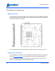
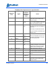
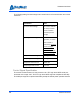
ThingMagic Nano Digital Connector Signal Definition
Edge Via
Pin #
Signal
Signal
Direction
(In/Out of
ThingMagic
Nano)
Notes
1-9, 18-19 GND Signal Return Must connect all GND pins to ground
as they also serve to remove heat
from the module
10 Vout DC Power
Output
3.4V DC output. Maximum load 5 mA.
Turns off when ENABLE is pulled low.
Leave unconnected if not used.
11 ENABLE Enable/Shut-
down
TTL input that turns the module off
and reduces its power consumption to
nearly zero.
Hi=Enable, Low=Shutdown module
If left unconnected, module will stay in
ENABLE state.
12 GPIO1 Bidirectional
GPIO
Each line configurable as input or out-
put interface (by default it is an input
with internal pull-down).
13 GPIO2 Bidirectional
GPIO
14 GPIO3 Bidirectional
GPIO
15 GPIO4 Bidirectional
GPIO
16,17 Vin Power Supply
Input
3.3 to 5.5VDC. Pins 16 and 17 are
internally connected. Connect the DC
power source to both pins to ensure
sufficient current carrying capacity.
20 UART_TX Out UART Serial output, 3.3V logic
21 UART_RX In UART Serial input, 3.3V logic. Must be
low when module is powered on or off.
22-28 RFU Reserved Reserved for future use - leave uncon-
nected
39 RF RF Transmit
and Receive
Interface to antenna
37-38, 40-41 GND RF Ground Must connect all GND pins to ground
as they also serve to remove heat
from the module