A DIVISION OF TRIMBLE 875-0077-01 Rev E ThingMagic Nano Design Guide For ThingMagic Nano with Firmware Ver. 1.3.
A DIVISION OF TRIMBLE Government Limited Rights Notice: All documentation and manuals were developed at private expense and no part of it was developed using Government funds. The U.S. Governmentʼs rights to use, modify, reproduce, release, perform, display, or disclose the technical data contained herein are restricted by paragraph (b)(3) of the Rights in Technical Data — Noncommercial Items clause (DFARS 252.227-7013(b)(3)), as amended from time-to-time.
A DIVISION OF TRIMBLE Revision Table Date Version Description 3/2015 01 Draft 1 Partial Draft for early-access release 4/2015 01 REV A First Release for prototype units with 1.3.1 firmware 4/2015 01 Rev B Second release for GA units with version 1.3.
A DIVISION OF TRIMBLE 4
Communication Regulation Information A DIVISION OF TRIMBLE Communication Regulation Information ! C A U T I O N ! ! Please contact ThingMagic support - support@thingmagic.com - before beginning the process of getting regulatory approval for a finished product using the ThingMagic Nano.
ThingMagic Nano Regulatory Information A DIVISION OF TRIMBLE W A R N I N G ! Operation of the ThingMagic Nano module requires professional installation to correctly set the TX power for the RF cable and antenna selected. This transmitter module is authorized to be used in other devices only by OEM integrators under the following conditions: 1.
ThingMagic Nano Regulatory Information A DIVISION OF TRIMBLE “This device complies with Part 15....” AND “Any changes or modifications to the transmitting module not expressly approved by ThingMagic Inc. could void the user’s authority to operate this equipment” “ End Product Labeling The final end product must be labeled in a visible area with the following: “Contains Transmitter Module FCC ID: QV5MERCURY6EN” or “Contains FCC ID: QV5MERCURY6EN.
ThingMagic Nano Regulatory Information A DIVISION OF TRIMBLE at least 21 cm from all persons and must not be collocated or operating in conjunction with any other antenna or transmitter. End Product Labeling The final end product must be labeled in a visible area with the following: “Contains ThingMagic Inc.
ThingMagic Nano Regulatory Information A DIVISION OF TRIMBLE cm de toute personne et ne doivent pas être installé en proximité ou utilisé en conjonction avec un autre antenne ou transmetteur. Marquage sur l’ étiquette du produit complet dans un endroit visible: "Contient ThingMagic transmetteur, FCC ID: QV5MERCURY6EN (IC:5407A-MERCURY6EN)" Authorized Antennas This device has been designed to operate with the antennas listed in Authorized Antennas.
ThingMagic Nano Regulatory Information A DIVISION OF TRIMBLE 10
A DIVISION OF TRIMBLE Contents Communication Regulation Information . . . . . . . . . . . . . . . . . . . . . . . . . . . . . . . . . . . . . . . . . . . . . . 5 ThingMagic Nano Regulatory Information . . . . . . . . . . . . . . . . . . . . . . . . . . . . . . . . . . . . . . . . . . . . 5 Federal Communication Commission Interference Statement. . . . . . . . . . . . . . . . . . . . . . . . . . . . . 5 Industry Canada . . . . . . . . . . . . . . . . . . . . . . . . . . . . . . . . . . . . . . . . . . . .
A DIVISION OF TRIMBLE Receiver Adjacent Channel Rejection . . . . . . . . . . . . . . . . . . . . . . . . . . . . . . . . . . . . . . . . . . . . . . 38 Environmental Specifications . . . . . . . . . . . . . . . . . . . . . . . . . . . . . . . . . . . . . . . . . . . . . . . . . . . . . 39 Thermal Considerations . . . . . . . . . . . . . . . . . . . . . . . . . . . . . . . . . . . . . . . . . . . . . . . . . . . . . . . . . 39 Thermal Management . . . . . . . . . . . . . . . . . . . . . . . . . . . . . . .
A DIVISION OF TRIMBLE Frequency Hop Table. . . . . . . . . . . . . . . . . . . . . . . . . . . . . . . . . . . . . . . . . . . . . . . . . . . . . . . . . . . 74 Protocol Support . . . . . . . . . . . . . . . . . . . . . . . . . . . . . . . . . . . . . . . . . . . . . . . . . . . . . . . . . . . . . . . . 76 Gen2 (ISO 18000-6C) Protocol . . . . . . . . . . . . . . . . . . . . . . . . . . . . . . . . . . . . . . . . . . . . . . . . . . . 76 Gen2 Protocol Configuration Options . . . . . . . . . . . . . . . .
A DIVISION OF TRIMBLE FAULT_FLASH_WRITE_TO_NON_ERASED_AREA – 304h . . . . . . . . . . . . . . . . . . . . . . . . . 93 FAULT_FLASH_WRITE_TO_ILLEGAL_SECTOR – 305h . . . . . . . . . . . . . . . . . . . . . . . . . . . . 93 FAULT_FLASH_VERIFY_FAILED – 306h . . . . . . . . . . . . . . . . . . . . . . . . . . . . . . . . . . . . . . . . 94 Protocol Faults . . . . . . . . . . . . . . . . . . . . . . . . . . . . . . . . . . . . . . . . . . . . . . . . . . . . . . . . . . . . . . . . .
A DIVISION OF TRIMBLE System Errors . . . . . . . . . . . . . . . . . . . . . . . . . . . . . . . . . . . . . . . . . . . . . . . . . . . . . . . . . . . . . . . . . 108 FAULT_SYSTEM_UNKNOWN_ERROR – 7F00h . . . . . . . . . . . . . . . . . . . . . . . . . . . . . . . . . 108 FAULT_TM_ASSERT_FAILED – 7F01h. . . . . . . . . . . . . . . . . . . . . . . . . . . . . . . . . . . . . . . . . 108 Appendix B: Getting Started - Dev Kit . . . . . . . . . . . . . . . . . . . . . . . . . . . . . . . .
A DIVISION OF TRIMBLE 16 Contents
A DIVISION OF TRIMBLE Introduction The ThingMagic® Nano® embedded module is an RFID reader that you can integrate with other systems to create RFID-enabled products. Applications to control the ThingMagic Nano modules and derivative products can be written using the high level MercuryAPI. The MercuryAPI supports Java, “.NET” and C programming environments.
Specifications Summary A DIVISION OF TRIMBLE Specifications Summary The table below summarizes the specifications of the ThingMagic Nano module. Many of these specifications are discussed in further detail in the Hardware Overview chapter. Physical 22 mm L x 26 mm W x 3.0 mm H Dimensions (.866 in L x 1.024 in W x 0.
Specifications Summary A DIVISION OF TRIMBLE Pre-configured for the following regions: ▪ FCC (NA, SA) 917.4-927.2 MHz ▪ ETSI (EU) 865.6-867.6 MHz ▪ TRAI (India) 865-867 MHz Regulatory ▪ KCC (Korea) 917-923.5 MHz ▪ MIC (Japan) 916.8 – 923.4 MHz ▪ ACMA (Australia) 920-926 MHz ▪ SRRC-MII (P.R.China) 920.1-924.
Specifications Summary A DIVISION OF TRIMBLE DC Voltage: 3.3 to 5.5 V for +25 dBm out 3.7 to 5.5 V for +27 dBm out DC Power Nominal DC power consumption when reading: Required 3.6 W@ 5 VDC for +27 dBm out 3.3 W@ 5 VDC for +25 dBm out 1.5 W@ 5 VDC for 0 dBm out ▪ 0.84 W in ready mode Idle Power ▪ 0.015 W in sleep mode Consumption ▪ 0.00025 W in shutdown mode Environment ▪ FCC 47 CFR Ch. 1 Part 15 Certification ▪ Industrie Canada RSS-21 0 ▪ ETSI EN 302 208 v1.4.1 Operating Temp.
A DIVISION OF TRIMBLE Hardware Overview The following section provides detailed specifications of the ThingMagic Nano hardware including: Hardware Interfaces DC Power Requirements RF Characteristics Environmental Specifications Authorized Antennas Physical Dimensions Tape-and-Reel Dimensions Hardware Overview 21
Hardware Interfaces A DIVISION OF TRIMBLE Hardware Interfaces Module Pin-out Connections are made to the module using 41 edge pads (“vias”) that allow the module to be surface mounted to a main board. Here is a bottom view of the module, showing the numerical interfaces of the module: The document sections that follow explain in detail how these connections are used. Antenna Connections The ThingMagic Nano supports one monostatic bidirectional RF antenna through edge vias.
Hardware Interfaces A DIVISION OF TRIMBLE Antenna Requirements The performance of the ThingMagic Nano is affected by antenna quality. Antennas that provide good 50 ohm match at the operating frequency band perform best. Specified performance is achieved with antennas providing 17 dB return loss (VSWR of 1.33) or better across the operating band. Damage to the module will not occur for any return loss of 1 dB or greater.
Hardware Interfaces A DIVISION OF TRIMBLE Digital/Power Interfaces The edge “via” connections provides power, serial communications signals, an enable control, and access to the GPIO lines to the ThingMagic Nano module.
Hardware Interfaces A DIVISION OF TRIMBLE ThingMagic Nano Digital Connector Signal Definition Edge Via Pin # Signal Signal Direction (In/Out of ThingMagic Nano) Notes 1-9, 18-19 GND Signal Return Must connect all GND pins to ground as they also serve to remove heat from the module 10 Vout DC Power Output 3.4V DC output. Maximum load 5 mA. Turns off when ENABLE is pulled low. Leave unconnected if not used.
Hardware Interfaces A DIVISION OF TRIMBLE The following table gives the Voltage and Current limits for all communication and control interfaces: Specification Limits Input Low-level Voltage 1.0 V max to indicate low state; no lower than 0.3 V below ground to prevent damage Input High-level Voltage 1.9 V min to indicate high state; 3.7 V max when module is powered up, no more than 0.3 V higher than Vout when module is turned off to prevent damage. Output Low-level Voltage 0.3 V typ, 0.
Hardware Interfaces A DIVISION OF TRIMBLE TTL Level UART Interface Only three pins are required for serial communication (TX, RX, and GND). Hardware handshaking is not supported.This is a TTL interface; a level converter is necessary to connect to devices that use a 12V RS232 interface. The RX line is a 3.3 volt logic CMOS input and is internally pulled up with a resistance value of between 20 and 60 kOhms (40 kOhms nominal).
Hardware Interfaces A DIVISION OF TRIMBLE a 3.3 volt logic CMOS input and is internally pulled down with a resistance value of between 20 and 60 kOhms (40 kOhms nominal). Lines configured as inputs must be low whenever the module is turned off and low at the time the module is turned on. GPIOs may be reconfigured individually after power up to become outputs. Lines configured as outputs consume no excess power if the output is left open.
DC Power Requirements A DIVISION OF TRIMBLE DC Power Requirements The module is specified to operate with DC input levels of between 3.3 and 5.5 V. All specifications are maintained as long as the total input current is below 1 A. At 1 A, the internal Voltage regulatorʼs protection circuit allows no more current to be taken in. This 1A current limit will be reached slightly sooner if current is drawn out the Vout line or if the GPIO lines are supplying current to external circuits.
DC Power Requirements A DIVISION OF TRIMBLE Note Maximum power may have to be reduced to meet regulatory limits, which specify the combined effect of the module, antenna, cable and enclosure shielding of the integrated product. As shown in the chart, the current draw when the RF output level is set to +27 dBm reaches the limit of 1A when the DC input voltage is below 3.7 V. Below the 3.7 VDC input level, the RF level will no longer reach 27 dBm, although no error message will be returned.
DC Power Requirements A DIVISION OF TRIMBLE below shows the impact of the input DC Voltage on the RF output level for +25 dBm and +27 dBm RF power levels. The power drawn by the module is fairly constant, rising slightly as the DC Input Voltage is lowered.
DC Power Requirements A DIVISION OF TRIMBLE decrease, but this is because the RF output level is no longer reflecting the desired setting. This chart shows these dependencies: Note: Power consumption is defined for operation into a 17 dB return loss load (VSWR of 1.33) or better. Power consumption may increase, up to 4 W, during operation into return losses worse than 17 dB and high ambient temperatures. Power consumption will also vary based on which of the Supported Regions is in use.
DC Power Requirements A DIVISION OF TRIMBLE 3.3 to 5.5 VDC Less than 25 mV pk-pk ripple all frequencies, Less than 11 mV pk-pk ripple for frequencies less than 100 kHz, No spectral spike greater than 5 mV pk-pk in any 1 kHz band. Idle DC Power Consumption When not actively transmitting, the ThingMagic Nano module falls back into one of 3 idle states, called “power modes”.
RF Characteristics A DIVISION OF TRIMBLE RF Characteristics RF Output Power The output power may be set to a separate value for read and write operations (for many tags, more power is required to write to read). The range of values for both settings is from 0 dBm to +27 dBm, in 0.01 dB increments. (For example, 27 dBm will be configured as “2700” in units of centi-dBm.) The modules are calibrated when they are manufactured in 0.
RF Characteristics A DIVISION OF TRIMBLE Additional variation may be experienced if the DC input Voltage and temperature changes while the module is operational. This chart shows the typical transmit output variation over frequency. The typical variation is less than +/-0.5 dBm for all transmit levels, across the entire frequency band. DC Input Voltage also affects the transmit output level accuracy. The typical variation is less than +/- 0.
RF Characteristics A DIVISION OF TRIMBLE settings at around 3.7 VDC input levels and the RF output level starts to drop for +25 dBm settings at around 3.3 VDC input levels. The output accuracy over temperature is typically +/- 0.75 dBm, with most variation occurring at lower transmit output power levels.
RF Characteristics A DIVISION OF TRIMBLE Receive Sensitivity The receive sensitivity is influenced by both user-defined settings and by external environmental factors. These factors are: Transmit Level Gen2 “M” setting Region of Operation Receive sensitivity is strongly influenced by the amount of interference caused by the readerʼs own transmit signal. This interference can be reduced by reducing the transmit level.
RF Characteristics A DIVISION OF TRIMBLE increasing the moduleʼs sensitivity. Lower “M” values send data at higher rates, decreasing the sensitivity somewhat. The region of operation is also a factor. The Nano has slightly better receive sensitivity in the regions that fall within the range of 865 to 868 MHz than in regions that fall within the range of 917 to 928 MHz. The following table gives the sensitivity for region and “M” value at a transmit output level of +27 dBm.
Environmental Specifications A DIVISION OF TRIMBLE Environmental Specifications Thermal Considerations The module will operate within its stated specifications over a temperature range o f -20 to +60 degrees C, measured at the ground plane that the ThingMagic Nano module is soldered to. It may be safely stored in temperatures ranging from -40 degrees C to +85 degrees C.
Environmental Specifications A DIVISION OF TRIMBLE Note The temperature level at which transmission is prevented, +85 C, is higher than the +60 C operating limit for two reasons: (1) The temperature indicated by the on-board sensor will always be higher than ambient temperature, due to heat generated by internal components, and (2) the temperature limit for transmission is chosen to prevent damage to the components, while the +60 C limit for operation is chosen to ensure that all specifications are met.
Environmental Specifications A DIVISION OF TRIMBLE Electro-Static Discharge (ESD) Specification The Electro-Static Discharge Immunity specifications for the ThingMagic Nano are as follows: IEC-61000-4-2 and MIL-883 3015.7 discharges direct to operational antenna port tolerates max 1 KV pulse. It will tolerate a 4 kV air discharge on the I/O and power lines. It is recommended that protective diodes be placed on the I/O lines as shown in the carrier board schematic diagram (see Hardware Integration).
Authorized Antennas A DIVISION OF TRIMBLE Authorized Antennas This device has been designed to operate with the antennas listed below, and having a maximum gain of 8.15 dBiL. Antennas not included in this list or having a gain greater than 8.15 dBiL are strictly prohibited for use with this device without regulatory approval. (Circularly polarized antennas can have a circular gain has high as 11.15 dBiC and still maintain a maximum linear gain of 8.15 dBiL.) The required antenna impedance is 50 ohms.
Authorized Antennas A DIVISION OF TRIMBLE antenna previously authorized under the same FCC ID, and must have similar in band and out of band characteristics (consult specification sheet for cut-off frequencies). If the antenna is of a different type or higher gain than those listed in the moduleʼs FCC filing, see ThingMagic Nano Authorized Antennas, a class II permissive change must be requested from the FCC. Contact us at support@thingmagic.com and we can help you though this process.
Physical Dimensions A DIVISION OF TRIMBLE Physical Dimensions The dimensions of the ThingMagic Nano module are shown in the following diagram and the table below: Attribute Value Width 22 +/-0.2 mm Length 26 +/-0.2 mm Height (includes PCB, shield, mask and labels) 3.0 maximum Mass 3.
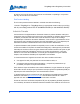
Physical Dimensions A DIVISION OF TRIMBLE Tape-and-Reel Dimensions The Nano is delivered in a tape-and-reel package. The reel measures 13 inches by 4 inches. The following drawing gives the dimensions of the tape.
Physical Dimensions A DIVISION OF TRIMBLE 46 Hardware Overview
70 :$1* -6 32/<67<5(1( ,9 176 ; 1DQR $R UG $QJOH VW $QJOH 6(&7,21 ; ; 352326(' (0%266(' &$55,(5 7$3( ',0(16,216 6&$/( *(1(5$/ 72/(5$1&( 3 , 7+,6 '5$:,1* &217$,16 ,1)250$7,21 7+$7 ,6 35235,(7$5< 72 & 3$.
SMT Reflow Profile A DIVISION OF TRIMBLE SMT Reflow Profile Short reflow profiles are recommended for soldering processes. Peak zone temperature should be adjusted high enough to ensure proper wetting and optimized forming of solder joints. Generally speaking, unnecessary long exposure and exposure to more than 245C should be avoided. To not overstress the assembly, the complete reflow profile should be as short as possible. An optimization considering all components on the application must be performed.
A DIVISION OF TRIMBLE Hardware Integration The ThingMagic® Nano® embedded module is an RFID reader that you can integrate with other systems to create RFID-enabled products. This chapter discusses topics relating to this, including requirements for a host board design and characteristics of the Nano Carrier Board that ThingMagic offers for use in Development Kits and for applications where standard connectors are required to interface the module with a host board.
Host Board Design A DIVISION OF TRIMBLE Host Board Design Landing Pads This diagram shows the position and recommended size of the landing pads (in dark green) and the heat-sink areas (in light green): Hardware design files are available on the Support web site (http://www.thingmagic.com/ manuals-firmware) for the “carrier board” that implements this layout.
Host Board Design A DIVISION OF TRIMBLE The ThingMagic Nano module mounts to the host board via the landing pads. These pads are at a pitch of 1.25 mm. The intention is for the ThingMagic Nano module is to use routed-through via connections with 0.7 mm diameter edge vias. The pads of the ThingMagic Nano module underside should align with the copper pads of the footprint, with a pad exposure extending outside the M6e-Nano edge be a nominal 0.5 mm. A 0.5 mm keep-out shall surround any non-ground pad.
Host Board Design A DIVISION OF TRIMBLE There is the potential for 24MHz harmonics radiating from pins 22 through 28 of the ThingMagic Nano. If emissions testing shows such harmonics, the easiest fix is to put bypass capacitors (typically 39 to 100pf) directly at the offending pins on the carrier board. Note that higher values are not necessarily better. The ideal capacitor value will have series resonance near the most offending frequency. 39pF has been good for around 900 MHz in sample board layouts.
ThingMagic Nano Carrier Board A DIVISION OF TRIMBLE ThingMagic Nano Carrier Board ThingMagic has created a Carrier Board for the ThingMagic Nano module, as an example of a host board for this module and to create an assembly that is compatible with the standard Development Kit main board. It has the size and dimensions of the M6e module (69 mm x 43 mm), and uses the same connector for power and control (Molex 532611571 - 1.25mm pin centers, 1 amp per pin rating.
ThingMagic Nano Carrier Board A DIVISION OF TRIMBLE of the M6e performs the same function as the ENABLE line in the Nano, but has reversed polarity. Pin Number Signal Signal Direction with respect to Carrier Board Notes 1,2 GND Power and Signal Return Must connect both pins to ground. 3.4 DC Power in Input 3.3 to 5.5 VDC; must connect both pins to the supply. 5 GPIO1 Bidirectional Same Specifications as Nano itself. 6 GPIO2 Bidirectional Same Specifications as Nano itself.
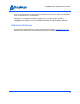
ThingMagic Nano Carrier Board A DIVISION OF TRIMBLE ThingMagic Nano can draw from its power source, potentially requiring slightly higher input voltage levels to achieve the highest RF output levels. The following page provides a schematic diagram for the Nano Carrier Board. Contact support@thingmagic.com to obtain this in a PDF file.
ThingMagic Nano Carrier Board A DIVISION OF TRIMBLE ! C A U T I O N ! ! The RX input line and all GPIO lines configured as inputs must be low when the module is turned off and low just before the module is turned on. If input lines are high at the time the module is being powered up, we have seen corruption of memory occur that cannot be remedied except at the factory.
ThingMagic Nano Carrier Board A DIVISION OF TRIMBLE Hardware Integration 57
A B M6e Pin Pin Pin Pin Pin Pin Pin Pin Pin Pin Pin Pin Pin Pin Pin Interface Pinout 1 GND 2 GND 3 +5V 4 +5V 5 GPIO1 6 GPIO2 7 GPIO3 8 GPIO4 9 RS-232_RX_TTL 10 RS-232_TX_TTL 11 USB_DM 12 USB_DP 13 USB_5VSENSE 14 SHUTDOWN 15 RESET 53261-1571 M1 M2 J6 VIN GND 7 1 2 3 4 5 6 7 8 9 10 11 12 13 14 15 5 R1 DNP 4 MH7 MH4 MH3 MH8 MH2 D2 TVS-4 Optional ESD Protection TVS-4 D3 DNP J5 DNP J3 1 2 3 1 2 3 SPI_MOSI__USBDM SPI_CLK__USBDP MH1 TVS-4 D1 GPIO4__VSENSE R2 DNP Jump Pin 1-2 for
ThingMagic Nano Carrier Board A DIVISION OF TRIMBLE Carrier Board Heat Sinking The ThingMagic Nano can run at full RF power at room temperature on stand-offs in the Dev Kit. If you wish to test the ThingMagic Nano under extreme temperature conditions, you may want to mount it on the heat spreader that is supplied with the Micro modules for the xPRESS Sensor Hub. Make sure it is assembled as shown in these pictures so no live signals are shorted to ground.
ThingMagic Nano Carrier Board A DIVISION OF TRIMBLE Note The Xpress Sensor Hub firmware does not support the Thingmagic Nano module at this time.
A DIVISION OF TRIMBLE Firmware Overview The following section provides detailed description of the ThingMagic Nano firmware components, including: Boot Loader Application Firmware Custom On-Reader Applications Firmware Overview 61
Boot Loader A DIVISION OF TRIMBLE Boot Loader The boot loader provides module functionality until the module application firmware can start up as well as when the module firmware is in the process of being updated. This program provides the low level hardware support for configuring communication settings, loading Application Firmware and storing data that needs to be remembered across reboots. When a module is powered up or reset, the boot loader code is automatically loaded and executed.
Application Firmware A DIVISION OF TRIMBLE Application Firmware The application firmware contains the tag protocol code along with all the command interpreters to set and get system parameters and perform tag operations. The application firmware is started automatically upon power up. Programming the ThingMagic Nano Applications to control the ThingMagic Nano module are written using the high level MercuryAPI. The MercuryAPI supports Java, “.NET” and C programming environments.
Custom On-Reader Applications A DIVISION OF TRIMBLE Custom On-Reader Applications The ThingMagic Nano does not support installing custom applications on the module. All reader configuration and control is performed using the documented MercuryAPI methods in applications running on a host processor.
A DIVISION OF TRIMBLE Communication Protocol The following section provides an overview of the low level serial communications protocol used by the ThingMagic Nano.
Serial Communication Protocol A DIVISION OF TRIMBLE Serial Communication Protocol ThingMagic does not support bypassing the MercuryAPI to send commands to the ThingMagic Nano module directly, but some information about this interface is useful when troubleshooting and debugging applications which interface with the MercuryAPI. The serial communication between MercuryAPI and the ThingMagic Nano is based on a synchronized command-response/master-slave mechanism.
Serial Communication Protocol A DIVISION OF TRIMBLE Reader-to-Host Communication The following diagram defines the format of the generic Response Packet sent from the reader to the host. The Response Packet is different in format from the Request Packet.
User Programming Interface A DIVISION OF TRIMBLE User Programming Interface The ThingMagic Nano does not support programming to the serial protocol directly. All user interaction with the ThingMagic Nano must be performed using the MercuryAPI. The MercuryAPI supports Java, “.NET” and C programming environments. The MercuryAPI Software Development Kit (SDK) contains sample applications and source code to help developers get started demoing and developing functionality.
A DIVISION OF TRIMBLE Functionality of the ThingMagic Nano The following section provides detailed descriptions of the ThingMagic Nano features and functionality that are supported through the MercuryAPI.
Regulatory Support A DIVISION OF TRIMBLE Regulatory Support ! C A U T I O N ! ! Please contact ThingMagic support - support@thingmagic.com - before beginning the process of getting regulatory approval for a finished product using the ThingMagic Nano. We can supply documents, test reports and certifications to the test house, which will greatly accelerate the process.
Regulatory Support A DIVISION OF TRIMBLE constraints are provided in the following table. Additional information on each region is provided in Regional Frequency Specifications. Region Regulatory Support Notes Narrow Band North America (“NA2”) FCC 47 CFG Ch. 1 Part 15 Industrie Canada RSS-210 Complies with all FCC regulations but uses a narrow frequency range: 917,400 kHz to 927,200 kHz European Union (“EU3”) Revised ETSI EN 302 208 By default EU3 will use four channels.
Regulatory Support A DIVISION OF TRIMBLE Peopleʼs Republic of China (PRC) SRRC, MII The PRC specifications defines more channels than are in the Nanoʼs default hop table. This is because the regulations limit channels from 920 to 920.5MHz and from 924.5 to 925.0MHz to transmit levels of 100mW and below. The default hop table uses only the center channels which allow 2W ERP, 1W conducted, power output.
Regulatory Support A DIVISION OF TRIMBLE take 7 to 10 milliseconds, all passive tags will enter the power-down state during a frequency hop, which affects their behavior, per the EPCglobal Gen2 specification. The ThingMagic Nano supports commands that allow channels to be removed from the hop table and additional channels to be defined (within limits) ! C A U T I O N ! ! Use these commands with extreme caution. It is possible to change the moduleʼs compliance with the regional channel settings.
Regulatory Support A DIVISION OF TRIMBLE Regional Frequency Specifications Region Frequency Quantization (kHz) Lowest Channel Limit (kHz) Highest Channel Limit (kHz) Number of Channels in Default Hop Table NA2 (Reduced FCC) 200 917,400 kHz 927,200 kHz 50 EU3 (ETSI) 100 865,600 kHz 867,600 kHz 4 IN (India) 100 865,000 kHz 867,000 kHz 5 KR2 (Korea) 100 917,000 kHz 923,500 kHz 6 PRC 125 920,125 kHz 924,875 kHz 16 AU (Australia) 250 920,000 kHz 926,000 kHz 10 NZ (New Zealand
Regulatory Support A DIVISION OF TRIMBLE Frequencies are used in the order of entries in the table, so if a random order is required, the frequencies must be pre-randomized before entering. If necessary for a region, the hop table are randomized to create a pseudo-random sequence of frequencies to use. This is done automatically using the default hop tables provided for each region.
Protocol Support A DIVISION OF TRIMBLE Protocol Support Unlike the M6e and Micro modules, the ThingMagic Nano does not have the ability to support tag protocols other then EPCglobal Gen2 (ISO 18000-6C). Future support for newer versions of the Gen2 protocol, such as ISO 18000-63 (Gen2V2), are possible.
Protocol Support A DIVISION OF TRIMBLE Unsupported Gen2 Functionality The ThingMagic Nano module firmware can perform some Gen2 functions as a standalone command, but cannot do so as part of an embedded TagOps command: Here is the list of supported standard Gen2 functions: As Embedded TagOPs As Stand-alone TagOPs Gen2 Read Data Yes Yes Gen2 Write Tag No Yes Gen2 Write Data No Yes Gen2 Lock Tag No Yes Gen2 Kill Tag No Yes Gen2 Block Write No Yes Gen2 Block Erase No Yes Gen2 Block Per
Protocol Support A DIVISION OF TRIMBLE NXP G2X and G2i Calibrate NXP G2i ChangeConfig Monza 4QT ReadWrite AMS/IDS SL900A Sensor Tag Commands 78 Functionality of the ThingMagic Nano
Unsupported Features A DIVISION OF TRIMBLE Unsupported Features Unlike other ThingMagic modules, the ThingMagic Nano module currently does not support gathering reader statistics independent of the meta data that can be gathered with tag reads. The statistics not supported include: RF On-time Noise Floor, Noise Floor with Transmit On Frequency Temperature Antenna Ports Current Protocol The ThingMagic Nano module currently does not support Save and Restore of settings.
Antenna Port A DIVISION OF TRIMBLE Antenna Port The ThingMagic Nano has one monostatic antenna port. This port is capable of both transmitting and receiving. The module also supports Using a Multiplexer, allowing up to 4 total logical antenna ports, controlled using two GPIO lines. Note The ThingMagic Nano does not support bistatic (separate transmit and receive port) operation.
Antenna Port A DIVISION OF TRIMBLE ONLY GPIO 1 Used for Antenna Switching GPIO Output 1 State Logical Antenna Setting Low 1 High 3 ONLY GPIO 2 Used for Antenna Switching GPIO Output 2 State Logical Antenna Setting Low 1 High 2 MercuryAPI allows you to assign your own port numbers to these logical ports so that the port labels are not confusing to the user. By default, antennas are activated sequentially, from lowest to highest, returning to the lowest whenever a new read command is executed.
Tag Handling A DIVISION OF TRIMBLE Tag Handling When the ThingMagic Nano performs inventory operations (MercuryAPI Read commands) data is stored in a Tag Buffer until retrieved by the client application, or data is streamed directly to the host if operating in Tag Streaming/Continuous Reading mode. Tag Buffer The ThingMagic Nano uses a dynamic buffer that depends on EPC length and quantity of data read. As a rule of thumb it can store a maximum of 48 96-bit EPC tags in the Tag Buffer at a time.
Tag Handling A DIVISION OF TRIMBLE Note The TTL Level UART Interface does not support control lines, so it is not possible for the module to detect a broken communications interface connection and stop streaming the tag results. Nor can the host signal that it wishes tag streaming to stop temporarily without stopping the reading of tags.
Tag Read Meta Data A DIVISION OF TRIMBLE Tag Read Meta Data In addition to the tag EPC ID resulting from ThingMagic Nano inventory operation each TagReadData (see MercuryAPI for code details) contains meta data about how, where and when the tag was read. The specific meta data available for each tag read is as follows: Meta Data Field Antenna ID Description The antenna on with the tag was read.
Power Management A DIVISION OF TRIMBLE Power Management The ThingMagic Nano is designed for power efficiency and offers several power management modes. When transmitting, the power consumption can be minimized by using the lowest RF power level that meets the application requirements, and powering the module with highest DC input Voltage. A “Power Mode” setting determines the power consumed during periods that the module is not actively transmitting. Power Modes - is set in /reader/powerMode.
Performance Characteristics A DIVISION OF TRIMBLE Performance Characteristics Event Response Times The following table provides information on how long common ThingMagic Nano operations take. An event response time is defined as the maximum time from the end of a command to the beginning of the action the command enables. For example, whenever appropriate, the time represents the delay between the last byte of a read command and the moment when an RF signal is detected at the antenna.
Common Error Messages A DIVISION OF TRIMBLE Appendix A: Error Messages This appendix discusses error messages that you might see in API transport logs or passed up by the API to the host program. Categories of messages include: Common Error Messages Bootloader Faults Flash Faults Protocol Faults Analog Hardware Abstraction Layer Faults Tag ID Buffer Faults System Errors Common Error Messages The following table lists the common faults discussed in this section.
Common Error Messages A DIVISION OF TRIMBLE Solution Make sure the number of arguments matches the data length. FAULT_INVALID_OPCODE – (101h) Cause The opCode received is invalid or not supported in the currently running program (bootloader or main application) or is not supported in the current version of code. Solution Check the following: Make sure the command is supported in the currently running program.
Common Error Messages A DIVISION OF TRIMBLE Solution Check the HW specifications for the supported powers and insure that the level is not exceeded. For the Nano, this limit is +27 dBm. FAULT_MSG_INVALID_FREQ_RECEIVED (104h) Cause A message was received by the reader to set the frequency outside the supported range Solution Make sure the host does not set the frequency outside this range or any other locally supported ranges.
Common Error Messages A DIVISION OF TRIMBLE FAULT_UNIMPLEMENTED_FEATURE - (109h) Cause Attempting to invoke a command not supported on this firmware or hardware. Solution Check the command being invoked against the documentation. FAULT_INVALID_BAUD_RATE - (10Ah) Cause When the baud rate is set to a rate that is not specified in the Baud Rate table, this error message is returned. Solution Check the table of specific baud rates and select a baud rate.
Bootloader Faults A DIVISION OF TRIMBLE Bootloader Faults The following table lists the common faults discussed in this section. Fault Message Code FAULT_BL_INVALID_IMAGE_CRC 200h FAULT_BL_INVALID_APP_END_ADDR 201h FAULT_BL_INVALID_IMAGE_CRC – 200h Cause When the application firmware is loaded the reader checks the image stored in flash and returns this error if the calculated CRC is different than the one stored in flash.
Flash Faults A DIVISION OF TRIMBLE Flash Faults The following table lists the common faults discussed in this section.
Flash Faults A DIVISION OF TRIMBLE FAULT_FLASH_UNDEFINED_ERROR – 302h Cause This is an internal error and it is caused by a software problem in module. Solution When this occurs make note of the operations you were executing, save FULL error response and send a test case reproducing the behavior to support@thingmagic.com. FAULT_FLASH_ILLEGAL_SECTOR – 303h Cause An erase or write flash command was received with the sector value and password not matching.
Flash Faults A DIVISION OF TRIMBLE Solution When this occurs make note of the operations you were executing, save FULL error response and send a test case reproducing the behavior to support@thingmagic.com. FAULT_FLASH_VERIFY_FAILED – 306h Cause The module received a write flash command that was unsuccessful because data being written to flash contained an uneven number of bytes.
Protocol Faults A DIVISION OF TRIMBLE Protocol Faults The following table lists the common faults discussed in this section.
Protocol Faults A DIVISION OF TRIMBLE FAULT_NO_TAGS_FOUND – (400h) Cause A command was received (such as like read, write, or lock) but the operation failed. There are many reasons that can cause this error to occur. Here is a list of possible reasons that could be causing this error: No tag in the RF field Read/write power too low Antenna not connected Tag is weak or dead Solution Make sure there is a good tag in the field and all parameters are set up correctly.
Protocol Faults A DIVISION OF TRIMBLE Solution This value is invalid or this version of SW does not support the protocol value. Check the documentation for the correct values for the protocols in use and that you are licensed for it. FAULT_WRITE_PASSED_LOCK_FAILED – 403h Cause During a Write Tag Data for ISO18000-6B or UCODE, if the lock fails, this error is returned. The write command passed but the lock did not. This could be a bad tag.
Protocol Faults A DIVISION OF TRIMBLE FAULT_PROTOCOL_WRITE_FAILED – 406h Cause An attempt to modify the contents of a tag failed. There are many reasons for failure. Solution Check that the tag is good and try another operation on a few more tags. FAULT_NOT_IMPLEMENTED_FOR_THIS_PROTOCOL – 407h Cause A command was received which is not supported by a protocol. Solution Check the documentation for the supported commands and protocols.
Protocol Faults A DIVISION OF TRIMBLE FAULT_GENERAL_TAG_ERROR – 40Ah Cause This error is used by the GEN2 module. This fault can occur if the read, write, lock, or kill command fails. This error can be internal or functional. Solution Make a note of the operations you were performing and contact ThingMagic at http:// support.thingmagic.com FAULT_DATA_TOO_LARGE – 40Bh Cause A command was received to Read Tag Data with a data value larger than expected or it is not the correct size.
Protocol Faults A DIVISION OF TRIMBLE FAULT_PROTOCOL_BIT_DECODING_FAILED - 40Fh Cause Attempt to operate on a tag with an EPC length greater than the Maximum EPC length setting. Solution Check the EPC length being written. FAULT_PROTOCOL_INVALID_EPC – 410h Cause This error is used by the GEN2 module indicating an invalid EPC value has been specified for an operation. This fault can occur if the read, write, lock, or kill command fails.
Protocol Faults A DIVISION OF TRIMBLE Solution Check the data that is being passed in the command resulting in this error. Try with a different tag. FAULT_GEN2_PROTOCOL_MEMORY_OVERRUN_BAD_PC 423h Cause This is an error returned by Gen2 tags. The specified memory location does not exist or the PC value is not supported by the Tag. Solution Check the data that is being written and where its being written to in the command resulting in this error.
Protocol Faults A DIVISION OF TRIMBLE FAULT_GEN2 PROTOCOL_NON_SPECIFIC_ERROR - 42Fh Cause This is an error returned by Gen2 tags. The tag does not support error specific codes. Solution Check the data that is being written and where its being written to in the command resulting in this error. Try with a different tag. FAULT_GEN2 PROTOCOL_UNKNOWN_ERROR - 430h Cause This is an error returned by ThingMagic Nano when no more error information is available about why the operation failed.
Analog Hardware Abstraction Layer Faults A DIVISION OF TRIMBLE Analog Hardware Abstraction Layer Faults FAULT_AHAL_INVALID_FREQ – 500h Cause A command was received to set a frequency outside the specified range. Solution Check the values you are trying to set and be sure that they fall within the range of the set region of operation. FAULT_AHAL_CHANNEL_OCCUPIED – 501h Cause With LBT enabled an attempt was made to set the frequency to an occupied channel. Solution Try a different channel.
Analog Hardware Abstraction Layer Faults A DIVISION OF TRIMBLE Solution Connect a detectable antenna. (Antenna must have some DC resistance.) (Does not apply to Micro or ThingMagic Nano as they do not detect antennas.) FAULT_TEMPERATURE_EXCEED_LIMITS – 504h Cause The module has exceeded the maximum or minimum operating temperature and will not allow an RF operation until it is back in range.
Analog Hardware Abstraction Layer Faults A DIVISION OF TRIMBLE Solution Use the correct antenna setting or change the reader configuration.
Tag ID Buffer Faults A DIVISION OF TRIMBLE Tag ID Buffer Faults The following table lists the common faults discussed in this section. Fault Message Code FAULT_TAG_ID_BUFFER_NOT_ENOUGH_TAGS_AVAILABLE – 600h 600h FAULT_TAG_ID_BUFFER_FULL – 601h 601h FAULT_TAG_ID_BUFFER_REPEATED_TAG_ID – 602h 602h FAULT_TAG_ID_BUFFER_NUM_TAG_TOO_LARGE – 603h 603h FAULT_TAG_ID_BUFFER_NOT_ENOUGH_TAGS_AVAILABLE – 600h Cause A command was received to get a certain number of tag ids from the tag id buffer.
Tag ID Buffer Faults A DIVISION OF TRIMBLE FAULT_TAG_ID_BUFFER_REPEATED_TAG_ID – 602h Cause The module has an internal error. One of the protocols is trying to add an existing TagID to the buffer. Solution Send a test case reproducing the behavior to support@thingmagic.com. FAULT_TAG_ID_BUFFER_NUM_TAG_TOO_LARGE – 603h Cause The module received a request to retrieve more tags than is supported by the current version of the software.
System Errors A DIVISION OF TRIMBLE System Errors FAULT_SYSTEM_UNKNOWN_ERROR – 7F00h Cause The error is internal. Solution Send a test case reproducing the behavior to support@thingmagic.com. FAULT_TM_ASSERT_FAILED – 7F01h Cause An unexpected Internal Error has occurred. Solution The error will cause the module to switch back to Bootloader mode. When this occurs make note of the operations you were executing, save FULL error response and send a test case reproducing the behavior to support@thingmagic.
A DIVISION OF TRIMBLE Appendix B: Getting Started - Dev Kit This appendix provides instructions on the use of the ThingMagic Nano Development Kit: Dev Kit Hardware Demo Application Notice on Restricted Use of the Dev Kit Dev Kit Hardware Included Components With the dev kit, you will receive the following components: The ThingMagic Nano module soldered onto carrier board Power/interface developers board One USB cable One antenna One coax cable One 9V power supply International power
Dev Kit Hardware A DIVISION OF TRIMBLE Sample tags One QuickStart Guide - Details on which documents and software to download to get up and running quickly, along with details on how to register for and contact support.
Dev Kit Hardware A DIVISION OF TRIMBLE “USB/RS232”. The one labeled “USB” is not supported by the ThingMagic Nano module. 2. Plug the power supply into the Dev Kitʼs DC power input connector. 3. The LED next to the DC input jack, labeled DS1, should light up. If it doesnʼt light up check jumper J17 to make sure the jumper is connecting pins 2 and 3 4.
Dev Kit Hardware A DIVISION OF TRIMBLE Dev Kit USB Interface USB/RS232 The USB interface (connector labeled USB/RS232) closest to the power plug is to the RS232 interface of the ThingMagic Nano through an FTDI USB to serial converter. The drivers for it are available at http://www.ftdichip.com/Drivers/VCP.htm Please follow the instructions in the installation guide appropriate for your operating system.
Dev Kit Hardware A DIVISION OF TRIMBLE Dev kit Jumpers J8 Jumpers to connect ThingMagic Nano I/O lines to dev kit. For added safety, you should remove all 3 jumpers for USB connections and the AUTO_BT connection to the module. These lines are not supported, but are connected to the ThingMagic Nano module for test purposes, so should be left unconnected for all applications. J19 The jumper at J19 that connects SHUTDOWN to ground must be REMOVED. With this jumper removed, the module is always operational.
Dev Kit Hardware A DIVISION OF TRIMBLE Make sure GPIO lines are correspondingly configured as input or outputs (see Configuring GPIO Settings). J13, J15 Not used. J14 Can be used to connect GPIO lines to external circuits. If used jumpers should be removed from J10, J11. J16 Jump pins 1 and 2 or 2 and 3 to reset dev kit power supply. Same as using switch SW1 except allows for control by external circuit. J17 Jump pins 1 and 2 to use the 5V INPUT and GND inputs to provide power.
Demo Application A DIVISION OF TRIMBLE Demo Application A demo application which supports multi-protocol reading and writing is provided in the MercuryAPI SDK package. The executable for this example is included in the MercuryAPI SDK package under /cs/samples/exe/Universal-Reader-Assistant.exe and is also available for direct download from rfid.thingmagic.com/dev kit.
Notice on Restricted Use of the Dev Kit A DIVISION OF TRIMBLE Notice on Restricted Use of the Dev Kit The Mercury6e Developers Kit (Dev Kit) is intended for use solely by professional engineers for the purpose of evaluating the feasibility of applications. The userʼs evaluation must be limited to use within a laboratory setting.
A DIVISION OF TRIMBLE Appendix C: Environmental Considerations This Appendix details environmental factors that should be considered relating to reader performance and survivability.
ElectroStatic Discharge (ESD) Considerations A DIVISION OF TRIMBLE ElectroStatic Discharge (ESD) Considerations W A R N I N G ! The ThingMagic Nano antenna port may be susceptible to damage from Electrostatic Discharge (ESD). Equipment failure can result if the antenna or communication ports are subjected to ESD. Standard ESD precautions should be taken during installation to avoid static discharge when handling or making connections to the ThingMagic Nano reader antenna or communication ports.
ElectroStatic Discharge (ESD) Considerations A DIVISION OF TRIMBLE the statistics of those intensities, there may always be the bigger zap waiting in the wings. For the bare ThingMagic Nano equipped with the mitigation methods described below, there will always be the rouge ESD discharge that exceeds any given mitigation, and results in failure. Fortunately, many installations will have some upper bound on the value of ESD events given the geometry of that installation.
ElectroStatic Discharge (ESD) Considerations A DIVISION OF TRIMBLE Verify R-TNC knurled threaded nuts are tight and stay tight. Donʼt use a thread locking compound that would compromise the grounding connection of the thread to thread mate. If there is any indication that field vibration might cause the R-TNC to loosen, apply RTV or other adhesive externally. Use antenna cables with double-shield outer conductors, or even full metallic shield semi-rigid cables.
ElectroStatic Discharge (ESD) Considerations A DIVISION OF TRIMBLE Note The SHP600+ is rated for the full +27dBm (0.5 W) output of the ThingMagic Nano reader. Care must be taken if it is operated at higher RF input levels at high temperatures. 90 V Lightning Arrestors, such as the Terrawave Solutions Model TW-LP-RPTNC-PBHJ have been shown to be effective in suppressing ESD. This model contains a gas discharge tube which must be replaced periodically.
Variables Affecting Performance A DIVISION OF TRIMBLE Variables Affecting Performance Reader performance may be affected by the following variables, depending on the site where your Reader is being deployed: Environmental Tag Considerations Multiple Readers Environmental Reader performance may be affected by the following environmental conditions: Metal surfaces such as desks, filing cabinets, bookshelves, and wastebaskets may enhance or degrade Reader performance.
Variables Affecting Performance A DIVISION OF TRIMBLE Tag Orientation: Most tags have folded dipole antennas. They read well when facing the antenna and when their long edge is oriented toward the antenna, but very poorly when their short edge is oriented toward the antenna. Tag Model: Many tag models are available. Each model has its own performance characteristics. Antenna Considerations Use a circularly polarized antenna.
Variables Affecting Performance A DIVISION OF TRIMBLE Note Performance tests conducted under typical operating conditions at your site are recommended to help you optimize system performance.