
User Manual
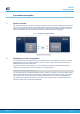
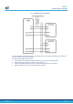
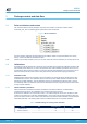


Table Of Contents

1 Functional description
1.1 System overview
The VL53L4CD system is composed of a hardware module and the Ultra Lite Driver software (VL53L4CD ULD)
running on a host (see figure below). The hardware module contains the ToF sensor. ST delivers the software
driver which is referred to in this document as "the driver". This document describes the functions of the driver
which are accessible to the host. These functions control the sensor and get the ranging data.
Figure 2. VL53L4CD system overview
1.2
Schematics and I2C configuration
The communication between driver and firmware is handled by I2C, with a capability of operating up to 1 MHz
(Fast Mode Plus). The implementation requires pull-ups on the SCL and SDA lines. Refer to the VL53L4CD
datasheet (DS13812) for more information.
By default, the sensor is programmed to run on I2C Fast Mode (up to 400 kHz). The Fast Mode Plus (up to
1 MHz) can be enabled using a platform compilation key in the file platform.h:
#define VL53L4CD_I2C_FAST_MODE_PLUS
The VL53L4CD device has a default I2C address of 0x52. However, it is possible to change the default address
to avoid conflict with other devices, or facilitate adding multiple VL53L4CD modules to the system for a greater
system Field of View. The I2C address can be reprogrammed using function VL53L4CD_SetI2CAddress().
The following figure represents the required connection to have multiple sensors on a single I2C bus. For the
schematics, please refer to the VL53L4CD datasheet.
UM2931
Functional description
UM2931 - Rev 1
page 2/15