
User Manual


Table Of Contents
5
The master reads one or more data bytes in succession. The
internal device address pointer auto increments with each
byte access.
6
The master strobes the acknowledge bit following each data
byte except for the final byte in the transfer before sending
the stop condition.
7
After the read cycle is done, the master sends a stop
condition to complete the operation.
Write Operation
After the master establishes communication with the LIDAR
device, writing to the LIDAR device operates as follows.
1
The master sends one or more 8-bit data blocks to the LIDAR
device. The internal device address pointer auto increments
with each byte access.
2
The LIDAR device sends an acknowledge bit to the master
when it receives and writes a valid data byte.
3
After the write cycle is done, the master sends a stop
condition to complete the operation.
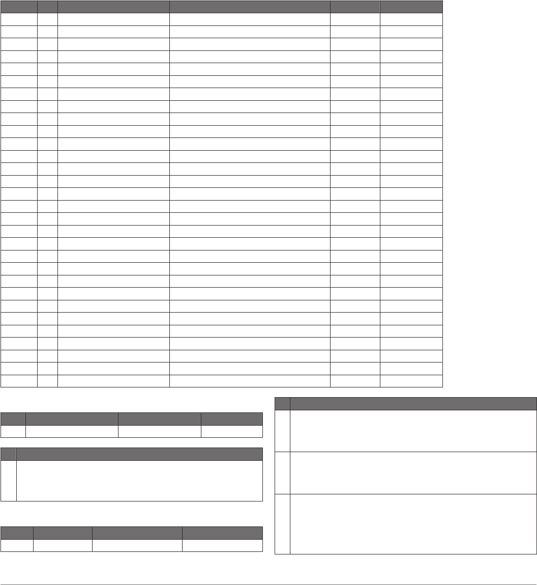
Control Register List
NOTE: Unless otherwise noted, all registers contain one byte and are read and write.
Address R/W Name Description Initial Value Details
0x00 W ACQ_COMMANDS Device command -- 0x00, page 5
0x01 R STATUS System status -- 0x01, page 5
0x05 R/W ACQUISITION_COUNT Maximum acquisition count 0xFF 0x05, page 6
0x10 R FULL_DELAY_LOW Distance measurement low byte -- 0x10, page 6
0x11 R FULL_DELAY_HIGH Distance measurement high byte -- 0x11, page 6
0x16 R UNIT_ID_0 Unit ID, byte 0 -- 0x16, page 6
0x16 W UNIT_ID_0_UNLOCK Write unit ID 0 for I2C address unlock -- 0x16, page 6
0x17 R UNIT_ID_1 Unit ID, byte 1 -- 0x17, page 6
0x17 W UNIT_ID_1_UNLOCK Write unit ID 1 for I2C address unlock -- 0x17, page 6
0x18 R UNIT_ID_2 Unit ID, byte 2 -- 0x18, page 6
0x18 W UNIT_ID_2_UNLOCK Write unit ID 2 for I2C address unlock -- 0x18, page 6
0x19 R UNIT_ID_3 Unit ID, byte 3 -- 0x19, page 6
0x19 W UNIT_ID_3_UNLOCK Write unit ID 3 for I2C address unlock -- 0x19, page 6
0x1A R/W I2C_SEC_ADDR Write new I2C address after unlock -- 0x1A, page 6
0x1B W I2C_CONFIG Default address response control 0x00 0x1B, page 6
0x1C R/W DETECTION_SENSITIVITY Peak detection threshold bypass 0x00 0x1C, page 6
0x30 R LIB_VERSION Read Garmin software library version string -- 0x30, page 7
0x52 R/W CORR_DATA Correlation record data control -- 0x52, page 7
0x72 R CP_VER_LO Coprocessor firmware version low byte -- 0x72, page 7
0x73 R CP_VER_HI Coprocessor firmware version high byte -- 0x73, page 7
0xE0 R BOARD_TEMPERATURE Board temperature -- 0xE0, page 7
0xE1 R HARDWARE_VERSION Board hardware version -- 0xE1, page 7
0xE2 R/W POWER_MODE Power state control 0xFF 0xE2, page 7
0xE3 R/W MEASUREMENT_INTERVAL Automatic measurement rate 0xFF 0xE3, page 7
0xE4 W FACTORY_RESET Reset default settings -- 0xE4, page 7
0xE5 R/W QUICK_TERMINATION Quick acquisition termination 0x08 0xE5, page 7
0xE6 W START_BOOTLOADER Start secure Bluetooth LE bootloader -- 0xE6, page 7
0xEA R/W ENABLE_FLASH_STORAGE Store register settings 0x00 0xEA, page 7
0xEB R/W HIGH_ACCURACY_MODE Improved accuracy setting 0x14 0xEB, page 8
0xEC R SOC_TEMPERATURE SoC temperature -- 0xEC, page 8
0x00
R/W Name Description Initial Value
W ACQ_COMMANDS Device command --
Bit Function
7:0 Write 0x03: Take distance measurement without receiver bias
correction
Write 0x04: Take distance measurement with receiver bias
correction
0x01
R/W Name Description Initial Value
R STATUS System status --
Bit Function
5 DC error flag
0: No error detected
1: An error was detected in correcting DC noise bias, and distance
measurements are expected to be inaccurate
4 DC bias done flag
0: The device is performing automatic DC noise bias corrections
1: DC noise is within tolerance, and the automatic DC noise bias
corrections are currently idle
3 Low power flag
0: Device is powered on. I2C commands can be issued at a normal
rate.
1: The device is in low power mode. To allow the device to power
on and perform the I2C command, a 10ms delay after each
command is recommended.
5