
Data Sheet


Bosch Sensortec | BME280 Data sheet
43 | 55
Modifications reserved | Data subject to change without notice
Document number: BST-BME280-DS002-15
Revision_1.6_092018
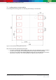
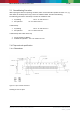
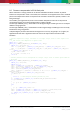
7.6 Landing pattern recommendation
For the design of the landing pattern, the following dimensioning is recommended:
Figure 21: Recommended landing pattern (top view)
Note: red areas demark exposed PCB metal pads.
In case of a solder mask defined (SMD) PCB process, the land dimensions should be defined
by solder mask openings. The underlying metal pads are larger than these openings.
In case of a non solder mask defined (NSMD) PCB process, the land dimensions should be
defined in the metal layer. The mask openings are larger than these metal pads.