
Data Sheet


Bosch Sensortec | BME280 Data sheet
39 | 55
Modifications reserved | Data subject to change without notice
Document number: BST-BME280-DS002-15
Revision_1.6_092018
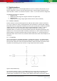
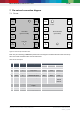
7.2 Connection diagram I
2
C
I2C address bit 0
GND: '0'; V
DDIO
: '1'
TOP VIEW
(pads not visible)
8
V
DD
7
GND
6
V
DDIO
5
SDO
C
1
V
DDIO
V
DD
C
2
1
GND
2
CSB
3
SDI
4
SCK
SDA
SCL
Vent hole
R
2
R
1
Figure 17: I²C connection diagram
Notes:
The recommended value for C
1
, C
2
is 100 nF
The value for the pull-up resistors R
1
, R
2
should be based on the interface timing and the bus
load; a normal value is 4.7 kΩ
A direct connection between CSB and V
DDIO
is required