
Data Sheet


Bosch Sensortec | BME280 Data sheet
38 | 55
Modifications reserved | Data subject to change without notice
Document number: BST-BME280-DS002-15
Revision_1.6_092018
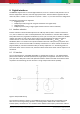
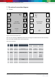
7. Pin-out and connection diagram
7.1 Pin-out
TOP VIEW
(pads not visible)
8
V
DD
7
GND
6
V
DDIO
5
SDO
BOTTOM VIEW
(pads visible)
1
GND
2
CSB
3
SDI
4
SCK
Pin 1
marker
1
GND
2
CSB
3
SDI
4
SCK
8
V
DD
7
GND
6
V
DDIO
5
SDO
Vent hole
Figure 16: Pin-out top and bottom view
Note: The pin numbering of BME280 is performed in the untypical clockwise direction when seen in top
view and counter-clockwise when seen in bottom view.
Table 35: Pin description
Pin
Name
I/O Type
Description
Connect to
SPI 4W
SPI 3W
I²C
1
GND
Supply
Ground
GND
2
CSB
In
Chip select
CSB
CSB
V
DDIO
3
SDI
In/Out
Serial data input
SDI
SDI/SDO
SDA
4
SCK
In
Serial clock input
SCK
SCK
SCL
5
SDO
In/Out
Serial data output
SDO
DNC
GND for
default
address
6
V
DDIO
Supply
Digital / Interface
supply
V
DDIO
7
GND
Supply
Ground
GND
8
V
DD
Supply
Analog supply
V
DD