
Data Sheet

Bosch Sensortec | BME280 Data sheet
16 | 55
Modifications reserved | Data subject to change without notice
Document number: BST-BME280-DS002-15
Revision_1.6_092018
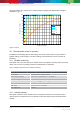
time
POR Data readout
Write
settings
Mode[1:0] = 01
Measurement H
time
current
I
DDSL
I
DDSB
I
DDP
I
DDH
POR
Measurement T
Measurement P
Write
settings
I
DDT
Measurement H
Measurement T
Measurement P
t
measure
Mode[1:0] = 01
cycle time = rate of force mode
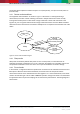
Figure 4: Forced mode timing diagram
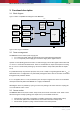
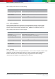
3.3.4 Normal mode
Normal mode comprises an automated perpetual cycling between an (active) measurement period
and an (inactive) standby period.
The measurements are performed in accordance to the selected measurement and filter options. The
standby time is determined by the setting t_sb[2:0] and can be set to between 0.5 and 1000 ms
according to Table 27.
The total cycle time depends on the sum of the active time (see chapter 9) and standby time t
standby
.
The current in the standby period (I
DDSB
) is slightly higher than in sleep mode. After setting the
measurement and filter options and enabling normal mode, the last measurement results can always
be obtained at the data registers without the need of further write accesses.
Using normal mode is recommended when using the IIR filter. This is useful for applications in which
short-term disturbances (e.g. blowing into the sensor) should be filtered. The timing diagram is shown
below:
Measurement H
time
current
I
DDSL
I
DDSB
I
DDP
I
DDH
POR Mode[1:0] = 11
Measurement P
Measurement T
Data readout
when needed
Write
settings
t
standby
I
DDT
Measurement H
Measurement P
Measurement T
t
measure
cycle time = t
measure
+ t
standby
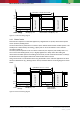
Figure 5: Normal mode timing diagram