
Data Sheet

Bosch Sensortec | BME280 Data sheet
15 | 55
Modifications reserved | Data subject to change without notice
Document number: BST-BME280-DS002-15
Revision_1.6_092018
The modes will be explained in detail in chapters 3.3.2 (sleep mode), 3.3.3 (forced mode) and 3.3.4
(normal mode).
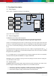
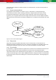
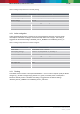
3.3.1 Sensor mode transitions
The supported mode transitions are shown in Figure 3. If the device is currently performing a
measurement, execution of mode switching commands is delayed until the end of the currently
running measurement period. Further mode change commands or other write commands to the
register ctrl_hum are ignored until the mode change command has been executed. Mode transitions
other than the ones shown below are tested for stability but do not represent recommended use of the
device.
Power OFF
(V
DD
or V
DDIO
= 0)
V
DD
and V
DDIO
supplied
Mode
[
1
:
0
] =
00
Mode[
1
:
0
] =
01
Sleep
Normal
(cyclic standby and
measurement periods)
Mode
[
1
:
0
] =
11
Forced
(one measurement
period)
Mode[1:0] = 01
Figure 3: Sensor mode transition diagram
3.3.2 Sleep mode
Sleep mode is entered by default after power on reset. In sleep mode, no measurements are
performed and power consumption (I
DDSM
) is at a minimum. All registers are accessible; Chip-ID and
compensation coefficients can be read. There are no special restrictions on interface timings.
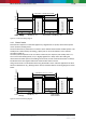
3.3.3 Forced mode
In forced mode, a single measurement is performed in accordance to the selected measurement and
filter options. When the measurement is finished, the sensor returns to sleep mode and the
measurement results can be obtained from the data registers. For a next measurement, forced mode
needs to be selected again. This is similar to BMP180 operation. Using forced mode is recommended
for applications which require low sampling rate or host-based synchronization. The timing diagram is
shown below.