
Data Sheet


VCNL4040
www.vishay.com
Vishay Semiconductors
Rev. 1.4, 02-Mar-15
9
Document Number: 84274
For technical questions, contact: sensorstechsupport@vishay.com
THIS DOCUMENT IS SUBJECT TO CHANGE WITHOUT NOTICE. THE PRODUCTS DESCRIBED HEREIN AND THIS DOCUMENT
ARE SUBJECT TO SPECIFIC DISCLAIMERS, SET FORTH AT www.vishay.com/doc?91000
Note
• All of reserved register are used for internal test. Please keep as default setting.
Command Register Format
VCNL4040 provides an 8-bit command register for ALS and PS controlling independently. The description of each command
format is shown in following tables.
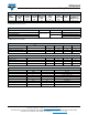
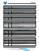
TABLE 1 - COMMAND CODE AND REGISTER DESCRIPTION
COMMAND
CODE
DATE BYTE
LOW / HIGH
REGISTER
NAME
R / W
DEFAULT
VALUE
FUNCTION DESCRIPTION
0x00
L ALS_CONF R / W 0x01 ALS integration time, persistence, interrupt, and function enable / disable
H Reserved R / W 0x00 Reserved
0x01
L ALS_THDH_L R / W 0x00 ALS high interrupt threshold LSB byte
H ALS_THDH_M R / W 0x00 ALS high interrupt threshold MSB byte
0x02
L ALS_THDL_L R / W 0x00 ALS low interrupt threshold LSB byte
H ALS_THDL_M R / W 0x00 ALS low interrupt threshold MSB byte
0x03
L PS_CONF1 R / W 0x01 PS duty ratio, integration time, persistence, and PS enable / disable
H PS_CONF2 R / W 0x00 PS output resolution selection, PS interrupt trigger method
0x04
L PS_CONF3 R / W 0x00 PS smart persistence, active force mode
H PS_MS R / W 0x00
White channel enable / disable, PS mode selection, PS protection setting,
and LED current selection
0x05
L PS_CANC_L R / W 0x00 PS cancellation level setting
H PS_CANC_M R / W 0x00 PS cancellation level setting
0x06
L PS_THDL_L R / W 0x00 PS low interrupt threshold setting LSB byte
H PS_THDL_M R / W 0x00 PS low interrupt threshold setting MSB byte
0x07
L PS_THDH_L R / W 0x00 PS high interrupt threshold setting LSB byte
H PS_THDH_M R / W 0x00 PS high interrupt threshold setting MSB byte
0x08
L PS_Data_L R 0x00 PS LSB output data
H PS_Data_M R 0x00 PS MSB output data
0x09
L ALS_Data_L R 0x00 ALS LSB output data
H ALS_Data_M R 0x00 ALS MSB output data
0x0A
L White_Data_L R 0x00 White LSB output data
H White_Data_M R 0x00 White MSB output data
0x0B
L Reserved R 0x00 Reserved
H INT_Flag R 0x00 ALS, PS interrupt flags
0x0C
L ID_L R 0x86 Device ID LSB
H ID_M R 0x01 Device ID MSB
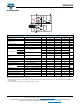
TABLE 2 - REGISTER: ALS_CONF DESCRIPTION
REGISTER NAME COMMAND CODE: 0x00_L (0x00 DATA BYTE LOW)
Command Bit76543210
REGISTER: ALS_CONF COMMAND CODE: 0x00_L (0x00 DATA BYTE LOW)
Command Bit Description
ALS_IT 7 : 6
(0 : 0) = 80 ms; (0 : 1) = 160 ms; (1 : 0) = 320 ms; (1 : 1) = 640 ms
ALS integration time setting, longer integration time has higher sensitivity
Reserved 5 : 4 Default = (0 : 0)
ALS_PERS 3 : 2
(0 : 0) = 1, (0 : 1) = 2, (1 : 0) = 4, (1 : 1) = 8
ALS interrupt persistence setting
ALS_INT_EN 1 0 = ALS interrupt disable, 1 = ALS interrupt enable
ALS_SD 0 0 = ALS power on, 1 = ALS shut down, default = 1