
Data Sheet


VCNL4040
www.vishay.com
Vishay Semiconductors
Rev. 1.4, 02-Mar-15
8
Document Number: 84274
For technical questions, contact: sensorstechsupport@vishay.com
THIS DOCUMENT IS SUBJECT TO CHANGE WITHOUT NOTICE. THE PRODUCTS DESCRIBED HEREIN AND THIS DOCUMENT
ARE SUBJECT TO SPECIFIC DISCLAIMERS, SET FORTH AT www.vishay.com/doc?91000
Digital Interface
VCNL4040 applies single slave address 0x60 (HEX) of 7-bit addressing following I
2
C protocol. As figure 12 shows, VCNL4040’s
I
2
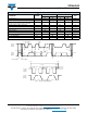
C command format is simple for read and write operations between VCNL4040 and the host. The white sections indicate host
activity and the gray sections indicate VCNL4040’s acknowledgement of the host access activity. Write word and read word
protocol is suitable for accessing registers particularly for 16-bit data ALS and 12-bit / 16-bit PS data. Interrupt can be cleared
by reading data out from register: INT_Flag. All command codes should follow read word and write word protocols.
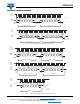
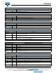
Fig. 12 - Write Word and Read Word Protocol
Function Description
VCNL4040 applies a 16-bit high resolution ALS that provides the best ambient light sensing capability down to 0.01 lux/step
which works well under a low transmittance lens design (dark lens). A flexible interrupt function of ALS (register: ALS_CONF)
is also supported. The INT signal will not be triggered by VCNL4040 if the ALS value is not over high INT threshold window level,
or lower than low INT threshold window level of ALS. VCNL4040 detects different light sources such as fluorescent light,
incandescent light, sunlight, and white LED with high accuracy ALS data output after detecting algorithm is implemented.
For proximity sensor function, VCNL4040 supports different kinds of mechanical designs to achieve the best proximity detection
performance for any color of object with more flexibility. The basic PS function settings, such as duty ratio, integration time,
interrupt, and PS enable / disable, and persistence, are handled by the register: PS_CONF1. Duty ratio controls the PS response
time. Integration time represents the duration of the energy being received. The interrupt is triggered when the PS detection
levels over the high threshold level setting (register: PS_THDH) or lower than low threshold (register: PS_THDL). If the interrupt
function is enabled, the host can react to the interrupt pin, instead of polling the PS data registers. The INT flag (register:
INT_Flag) indicates the type of interrupt that has been triggered, depending on the interrupt settings in the configuration
registers. PS persistence (PS_PERS) sets up the PS INT trigger conditions, defining the amount of consecutive hits required
before an interrupt event occurs. The intelligent cancellation level can be set on register: PS_CANC to reduce the cross talk
phenomenon.
VCNL4040 also supports an easy to use proximity detection logic mode, that triggers when the PS high threshold is exceeded
and automatically resets the interrupt pin when the proximity reading falls beneath the PS low threshold. This functionality can
be set in the register: PS_MS. A smart persistence is provided to be able to prevent false PS interrupt trigger events.
Descriptions of each of these parameters are shown in table 1.
S Slave Address
Wr
A Command Code A
Data Byte Low A Data Byte High A
17 811 1
818
P
11
Send Byte ɦ Write Command to VCNL4040
1
Slave Address
7
Wr
A Command Code A S Slave Address
Rd
A Data Byte Low A
Data Byte High A P
11 8 1
1
711
8
18
11
S
Receive Byte ɦ Read Data from VCNL4040
S = start condition
P = stop condition
A = acknowledge
Shaded area = VCNL4040 acknowledge