
Data Sheet


VCNL4040
www.vishay.com
Vishay Semiconductors
Rev. 1.4, 02-Mar-15
7
Document Number: 84274
For technical questions, contact: sensorstechsupport@vishay.com
THIS DOCUMENT IS SUBJECT TO CHANGE WITHOUT NOTICE. THE PRODUCTS DESCRIBED HEREIN AND THIS DOCUMENT
ARE SUBJECT TO SPECIFIC DISCLAIMERS, SET FORTH AT www.vishay.com/doc?91000
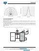
Fig. 10 - IRED Profile
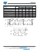
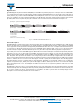
APPLICATION INFORMATION
Pin Connection with the Host
VCNL4040 integrates proximity sensor, ambient light Sensor, and IRED all together with I
2
C interface. It is very easy for the
baseband (CPU) to access PS and ALS output data via I
2
C interface without extra software algorithms. The hardware schematic
is shown in the following diagram.
Two additional capacitors in the circuit can be used for the following purposes: (1) the 0.1 μF capacitor near the V
DD
pin is used
for power supply noise rejection, (2) the 2.2 μF capacitor - connected to the anode - is used to prevent the IRED voltage from
instantly dropping when the IRED is turned on, and (3) 2.2 kΩ is suitable for the pull up resistor of I
2
C except for the 8.2 kΩ
applied on the INT pin.
Note
• Cathode (LED) and cathode (sensor): pins need to be connected together externally
Fig. 11 - Hardware Pin Connection Diagram
V
DD
Baseband
INT
INT
SCLK
CATHODE
(Sensor)
8
7
3
5
1
0.1uF
GND
SDAT
SCK
SDA
6
2.2KΩ2.2KΩ
V
DD_LED
2.2uF
8.2KΩ
V
Pull_up
2
CATHODE
(LED)
Anode
4
VCNL4040