
Data Sheet


VCNL4040
www.vishay.com
Vishay Semiconductors
Rev. 1.4, 02-Mar-15
3
Document Number: 84274
For technical questions, contact: sensorstechsupport@vishay.com
THIS DOCUMENT IS SUBJECT TO CHANGE WITHOUT NOTICE. THE PRODUCTS DESCRIBED HEREIN AND THIS DOCUMENT
ARE SUBJECT TO SPECIFIC DISCLAIMERS, SET FORTH AT www.vishay.com/doc?91000
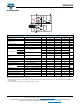
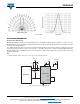
BLOCK DIAGRAM
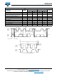
Notes
(1)
Test condition: V
DD
= 3.3 V, temperature: 25 °C
(2)
Maximum detection range to ambient light can be determined by ALS refresh time adjustment. Refer to table “ALS Resolution and Maximum
Detection Range”
(3)
Based on IRED on / off duty ratio = 1/40, 1/80, 1/160, and 1/320
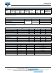
BASIC CHARACTERISTICS (T
amb
= 25 °C, unless otherwise specified)
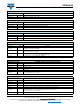
PARAMETER TEST CONDITION SYMBOL MIN. TYP. MAX. UNIT
Supply voltage V
DD
2.5 3.6 V
Supply current
Excluded LED driving I
DD
300 μA
Light condition = dark, V
DD
= 3.3 V I
DD
(SD) 0.2 μA
I
2
C supply voltage V
PULL UP
1.8 3.6 V
ALS shut down ALS disable, PS enable I
ALSSD
200 μA
PS shut down ALS enable, PS disable I
PSSD
260 μA
I
2
C signal input
Logic high
V
DD
= 3.3 V
V
IH
1.55
V
Logic low V
IL
0.4
Logic high
V
DD
= 2.6 V
V
IH
1.4
V
Logic low V
IL
0.4
Peak sensitivity wavelength of
ALS
λ
p
550 nm
Peak sensitivity wavelength of PS λ
pps
940 nm
Full ALS counts 16-bit resolution 65 535 steps
Full PS counts 12-bit / 16-bit resolution 4096 / 65 535 steps
ALS sensing tolerance White LED light source ± 10 %
Detectable
intensity
Minimum I
T
= 640 ms, 1 step
(1)(2)
0.0125
lx
Maximum I
T
= 80 ms, 65 535 step
(1)(2)
6553
ALS dark offset I
T
= 80 ms, normal sensitivity
(1)
03steps
PS detection range Kodak white card 0 200 mm
Operating temperature range T
amb
-40 +85 °C
Cathode (sensor) voltage 2.5 3.6 V
IRED driving current
(3)
200 mA
GND
Low Pass Filter
Temperature
Sensor
I
2
C Bus Logic
Control
ALS
16 bits
Data
Buffer
ALS
PD
PS
PD
DSP
PD Timing
Controller
Oscillator
LED Driver
PD
Buffer
LED_CATHODE
V
DD
SCLK
SDAT
INT
Anode
IR LED