
Data Sheet

VCNL4040
www.vishay.com
Vishay Semiconductors
Rev. 1.4, 02-Mar-15
13
Document Number: 84274
For technical questions, contact: sensorstechsupport@vishay.com
THIS DOCUMENT IS SUBJECT TO CHANGE WITHOUT NOTICE. THE PRODUCTS DESCRIBED HEREIN AND THIS DOCUMENT
ARE SUBJECT TO SPECIFIC DISCLAIMERS, SET FORTH AT www.vishay.com/doc?91000
Interruption (INT)
The VCNL4040 has an interrupt feature for both the PS and ALS channel. The purpose of the interrupt feature is to actively
inform the host once INT has been triggered. When the interrupt is enabled, the host does not need to continuously read the
data registers of the sensor, but instead can simply react to the interrupt pin. As long as the host enables ALS interrupt (register:
ALS_INT_EN) or PS interrupt (register: PS_INT) function, the level of INT pin (pin 6) is pulled low once an interrupt event has
been triggered. All registers are accessible even if INT is triggered.
ALS INT is triggered when ALS value crosses over the value set in register: ALS_THDH or below the value set by
register: ALS_THDL. PS INT is triggered when the PS value crosses over the value set in register: PS_THDH or falls below the
value set in register: PS_THDL. Which of these thresholds to react to, can be set by the PS_INT bits in the register: PS_CONF2.
Interruption Flag
Register: INT_Flag represents all of the interrupt trigger statuses for ALS and PS. If any of these flags trigger from “0” to “1”,
the INT pin will be pulled low. Once the host reads INT_Flag register, all the flags are cleared (reset to "0"), and the INT pin is
reset to high.
PROXIMITY DETECTION LOGIC OUTPUT MODE
VCNL4040 has a proximity detection logic mode, enabling the host to read the state of PS (near or far) simply by monitoring the
INT pin (pin 6). When this mode is selected, the INT pin is pulled low when an object is close to the sensor (value is above high
threshold) and is reset to high when the object moves away (value is below low threshold). Register: PS_THDH / PS_THDL
define where these threshold levels are set.
It should be noted that whenever the proximity detection logic mode has been enabled, the INT pin only reacts to proximity
interrupt events. If the host would like to use ALS INT function, the bit PS_MS in the register: PS_MS needs to be set to normal
operation mode (PS_MS = 0). In order for the proximity detection logic mode to function, one of the PS_INT bits in register:
PS_CONF2 must be enabled (“trigger when close”, “trigger when away”, or “trigger when close or away”). If PS_INT is set to
“INT Disable” the proximity detection logic mode will not function.
PROXIMITY DETECTION HYSTERESIS
A hysteresis is created by setting the low and high threshold values. With proximity detection logic mode disabled, an interrupt
event will trigger and stay triggered until it is cleared in the INT_Flag register. The register is cleared automatically once it is read.
If the interrupt flags are not cleared after an interrupt event has occurred, the VCNL4040 will not react to another interrupt event
until the INT-Flag register has been cleared. An example of this could be when turning on and off a backlight of a mobile display.
First the PS INT triggers when the PS value is over PS_THDH. The host switches off the panel backlight and then clears INT.
When PS value is less than PS_THDL, host switches on panel backlight.
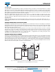
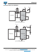
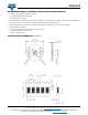
Fig. 13 - VCNL4040 Reference Circuit Connection with Host (Proximity Detection Logic Output Mode)
(VCNL4040 INT pin connecting to BB GPIO instead of INT pin)
V
DD
Baseband
GPIO
INT
SCLK
CATHODE
(Sensor)
8
7
3
5
1
0.1uF
GND
SDAT
SCK
SDA
6
2.2KΩ2.2KΩ
V
DD_LED
2.2uF
8.2KΩ
V
Pull_up
2
CATHODE
(LED)
Anode
4
VCNL4040