
Data Sheet

VCNL4040
www.vishay.com
Vishay Semiconductors
Rev. 1.4, 02-Mar-15
11
Document Number: 84274
For technical questions, contact: sensorstechsupport@vishay.com
THIS DOCUMENT IS SUBJECT TO CHANGE WITHOUT NOTICE. THE PRODUCTS DESCRIBED HEREIN AND THIS DOCUMENT
ARE SUBJECT TO SPECIFIC DISCLAIMERS, SET FORTH AT www.vishay.com/doc?91000
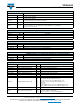
TABLE 9 - REGISTER: PS_MS DESCRIPTION
REGISTER: PS_MS COMMAND CODE: 0x04_H (0x04 DATA BYTE HIGH)
Command Bit Description
White_EN 7
0 = white channel enabled
1 = white channel disabled
PS_MS 6
0 = proximity normal operation with interrupt function
1 = proximity detection logic output mode enable
Reserved 5 : 3 ( 0 : 0 : 0 )
LED_I 2 : 0
(0 : 0 : 0) = 50 mA; (0 : 0 : 1) = 75 mA; (0 : 1 : 0) = 100 mA; (0 : 1 : 1) = 120 mA
(1 : 0 : 0) = 140 mA; (1 : 0 : 1) = 160 mA; (1 : 1 : 0) = 180 mA; (1 : 1 : 1) = 200 mA
LED current selection setting
TABLE 10 - REGISTER PS_CANC_L AND PS_CANC_M DESCRIPTION
COMMAND CODE: 0x05_L (0x05 DATA BYTE LOW) AND 0x05_H(0x05 DATA BYTE HIGH)
Register Bit Description
PS_CANC_L 7 : 0 0x00 to 0xFF, PS cancellation level setting_LSB byte
PS_CANC_M 7 : 0 0x00 to 0xFF, PS cancellation level setting_MSB byte
TABLE 11 - REGISTER: PS_THDL_L AND PS_THDL_M DESCRIPTION
COMMAND CODE: 0x06_L (0x06 DATA BYTE LOW) AND 0x06_H(0x06 DATA BYTE HIGH)
Register Bit Description
PS_THDL_L 7 : 0 0x00 to 0xFF, PS interrupt low threshold setting_LSB byte
PS_THDL_M 7 : 0 0x00 to 0xFF, PS interrupt low threshold setting_MSB byte
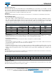
TABLE 12 - REGISTER: PS_THDH_L AND PS_THDH_M DESCRIPTION
COMMAND CODE: 0x07_L (0x07 DATA BYTE LOW) AND 0x07_H(0x07 DATA BYTE HIGH)
Register Bit Description
PS_THDH_L 7 : 0 0x00 to 0xFF, PS interrupt high threshold setting_LSB byte
PS_THDH_M 7 : 0 0x00 to 0xFF, PS interrupt high threshold setting_MSB byte
TABLE 13 - READ OUT REGISTER DESCRIPTION
Register Command Code Bit Description
PS_Data_L 0x08_L (0x08 data byte low) 7 : 0 0x00 to 0xFF, PS LSB output data
PS_Data_M 0x08_H (0x08 data byte high) 7 : 0 0x00 to 0xFF, PS MSB output data
ALS_Data_L 0x09_L (0x09 data byte low) 7 : 0 0x00 to 0xFF, ALS LSB output data
ALS_Data_M 0x09_H (0x09 data byte high) 7 : 0 0x00 to 0xFF, ALS MSB output data
White_Data_L 0x0A_L (0x0A data byte low) 7 : 0 0x00 to 0xFF, white LSB output data
White_Data_M 0x0A_H (0x0A data byte high) 7 : 0 0x00 to 0xFF, white LSB output data
Reserved 0x0B_L (0x0B data byte low) 7 : 0 Default = 0x00
INT_Flag 0x0B_H (0x0B data byte high)
7
6
5
4
3
2
1
0
Reserved
PS_SPFLAG, PS entering protection mode
ALS_IF_L, ALS crossing low THD INT trigger event
ALS_IF_H, ALS crossing high THD INT trigger event
Reserved
Reserved
PS_IF_CLOSE, PS rises above PS_THDH INT trigger event
PS_IF_AWAY, PS drops below PS_THDL INT trigger event
ID_L 0CH_L (0CH data byte low) 7 : 0 86H for MP version sample, device ID LSB byte
ID_M 0CH_H (0CH data byte high)
7 : 6
5 : 4
3 : 0
(0 : 0)
(0 : 0) Slave address = 0x60 (7-bit)
Version code (0 : 0 : 0 : 1), device ID MSB byte