
Data Sheet

AS7265x
Design Considerations
ams Application Note Page 10
[v1-5] 2018-May-23 Document Feedback
is minimized. The I
2
C bus specification also recommends that place VDD and/or GND between SDL
and SDA if the traces are longer than 10cm.
The length of I
2
C bus depends on the load of the bus and the speed you run at. The I
2
C bus
specification defines the maximum capacitance of the bus is 400pF. This bus capacitance limit is
specified to limit rise time reductions and allow operating at the rated frequency. In general, with lower
frequency and/or lower capacitance of the bus, you can have longer bus length.
For most of I
2
C bus designs, the capacitance limit should be not the problem at all. If you design
involves some unusual conditions, the specification has several strategies to cope with excess bus
capacitance. For example, higher drive outputs, bus buffers, switched pull-up circuit etc. Please refer
to the specification Section 7.2.
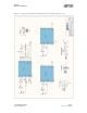
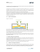
3.6 Optic Considerations
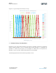
Figure 8. Aperture
Each AS7265x device has an open aperture on the surface. The diameter is 0.75mm and the package
field of view is ±20.5°. The light rays in the range as shown in above figure would arrive at the sensor.
Since AS7265x Multispectral Chipset consists of three AS7265x devices, an external optical device
might be needed so incident rays to each device is same.
As an open-aperture device, precautions must be taken to avoid particulate or solvent contamination
as a result of any manufacturing processes, including pick and place, reflow, cleaning, integration
assembly and/or testing.
4 Software Design Considerations
In most of system designs, AS72651 is controlled by a microcontroller. With the UART interface, the
controller could configure the devices and get the sensors data through some AT commands. The
software of microcontroller design would be simple.
The following sections would focus on I
2
C interface and the software of microcontroller design should
satisfy both I
2
C specification and AS7265x Multispectral Chipset register structure.
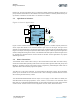
4.1 Features and Register Structure
AS72651 supports I
2
C both standard mode and fast mode. The addressing mode is 7+1-bit so when
the controller send a read command to AS72651, the salve address plus R/W bit should be 0x93 and
when sending a write command, it should be 0x92. Both read and write are single byte process.
DIE
Lens
Sensor
2.5mm
0.75mm
20.5°
12°
InputLightRaysRange